Previous Page Table of Contents Section Contents
Back
Index Next Page
LIFEPAK 500 automated external defibrillator Replacement Procedures
11-71
Replacing Patient Connector Harness—Monophasic AED Page 3 of 4
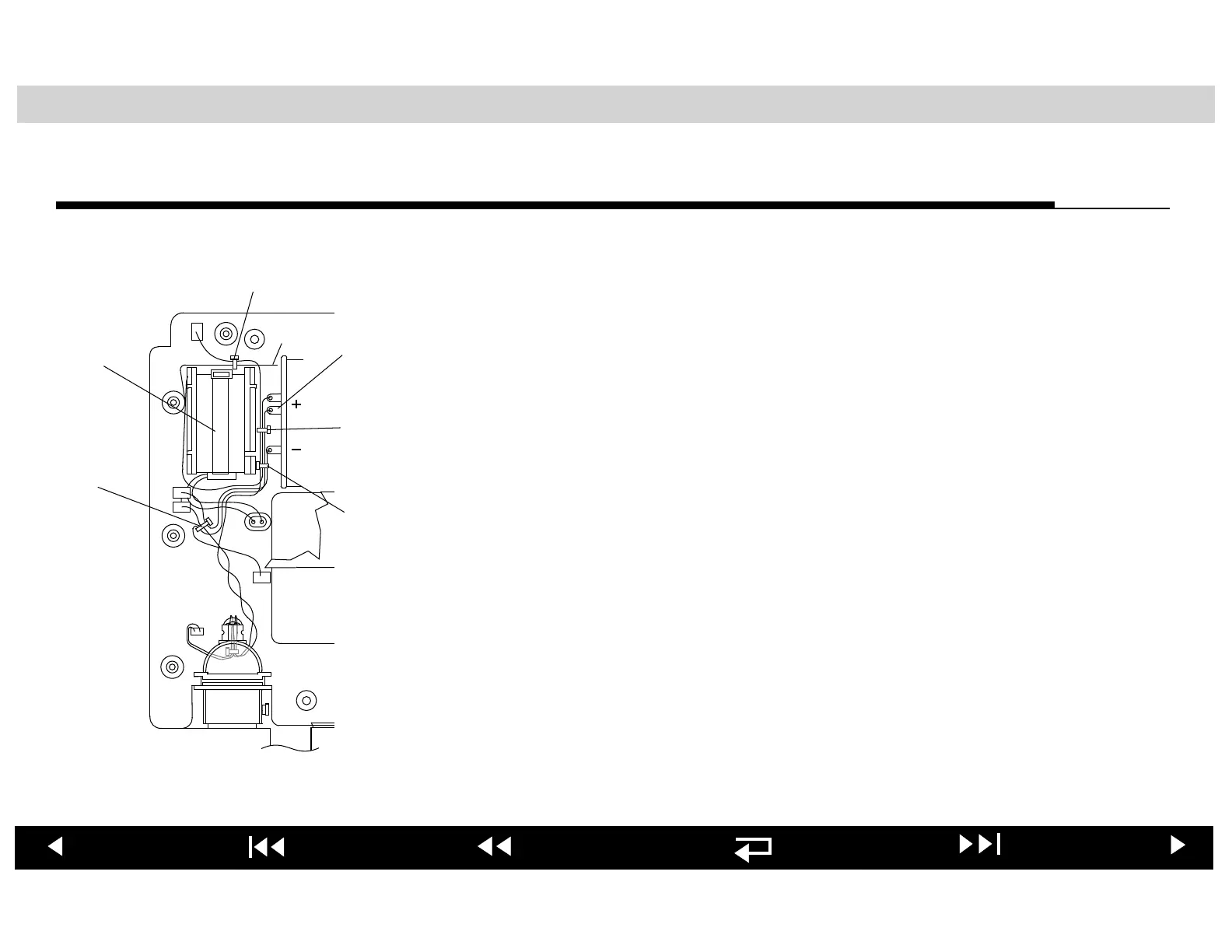
To route, dress, and tie-wrap wiring:
1. Position the Main PCB to the left of the lower enclosure, bottom surface
facing up.
Note: Refer to the Wire Routing and Tie-Wrap Placement—Monophasic
AED illustrations in the Parts Lists and Assembly Diagrams section and the
drawing at the left as you complete this procedure.
2. Connect:
– P1 to J1
– P4 to J4
3. Wrap the P2 wire two full turns clockwise around the P4 wire.
4. Route the P5(+) wire under P1 and P4 wires.
5. Connect P5(+) to J5.
Note: It is critical that the wire connected to J5 on the Main PCB is oriented so
that it exits the PCB and routes directly down toward the lower case cavity. It is
important that the wire does not loop back onto or near the PCB itself.
6. Loosely tie-wrap three wires: P5(+), P1, and P4 (Tie-Wrap #4).
7. Route the P2 wire over the capacitor terminals. Loosely tie-wrap four wires
over the (–) terminal: P13(+), P5(+), P1(–), and P2 (Tie-Wrap #3).
J5
J3
J4
J1
J2
J12
To J14
Tie-Wrap #1
Tie-
Wrap #4
Inductor
Tie-Wrap
Tie-
Wrap
#2
P13
Tie-
Wrap
#3