Project configuration
Operating Manual PSEN sc M 3.0/5.5 08-17
1005387-EN-05
| 36
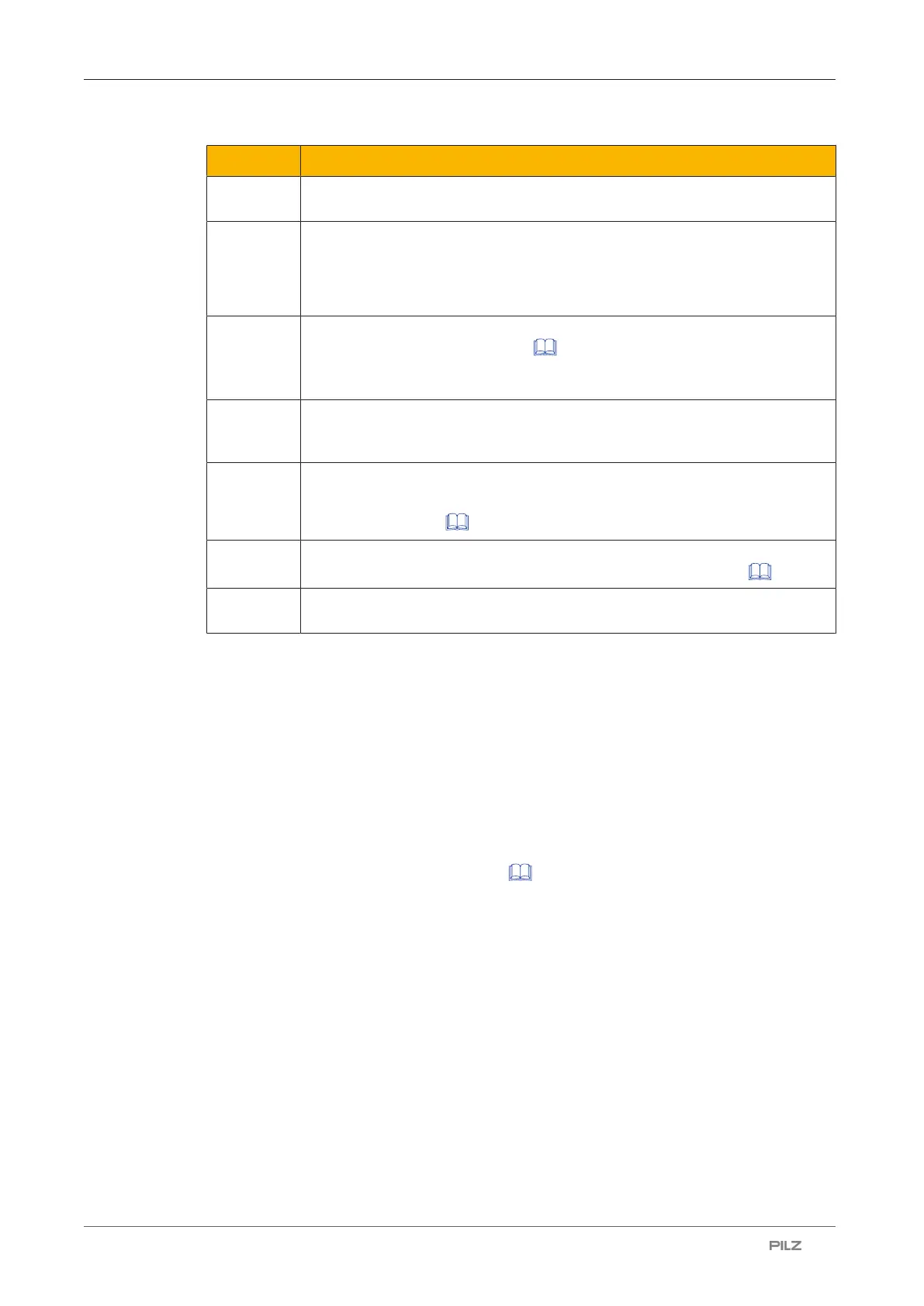
Icon Meaning
S Minimum distance in mm, measured from the start of the safety zone to the
danger source
K Approach speed with which the object to be detected is nearing the danger
zone in mm/s
K = 1600 mm/s when S > 500 mm
K = 2000 mm/s when S ≤ 500 mm
t
1
Overall response time of the safety laser scanner in seconds (see Calcula-
tion of the overall response time [ 43])
Time between the violation of a safety zone and signal change at the OSSD
output on the safety laser scanner
t
2
Machine's stopping time in seconds
The time required for the machine to stop after the signal at the OSSD out-
put changes
Z
T
General safety allowance
Standard value in the calculation and the teach-in function = 100 mm, (see
distance from walls [ 51])
Z
R
Allowance when installing near intense light sources or reflective surfaces
(see Distance to intense light sources and to reflective surfaces [ 50])
C Additional distance depending on the height of the scanning plane and the
detection capability
Determining the additional distance C depending on the height of the scanning plane
and the detection capability (see ENISO13855)
C = (1200 -0.4H)
Note:
} Permitted height H of the scanning plane
– Max. 1000 mm
– Min. h = 15(d-50) for d ≥ 70 mm
The height H must not be less than 0.
d = Resolution (see Technical details [ 127])
– If the height of the scanning plane is specified, the lowest permitted resolution d
r
can
be calculated.
d
r
= H/15 + 50
d
r
= lowest permitted resolution

 Loading...

