Wiring
Operating Manual PSEN sc M 3.0/5.5 08-17
1005387-EN-05
| 66
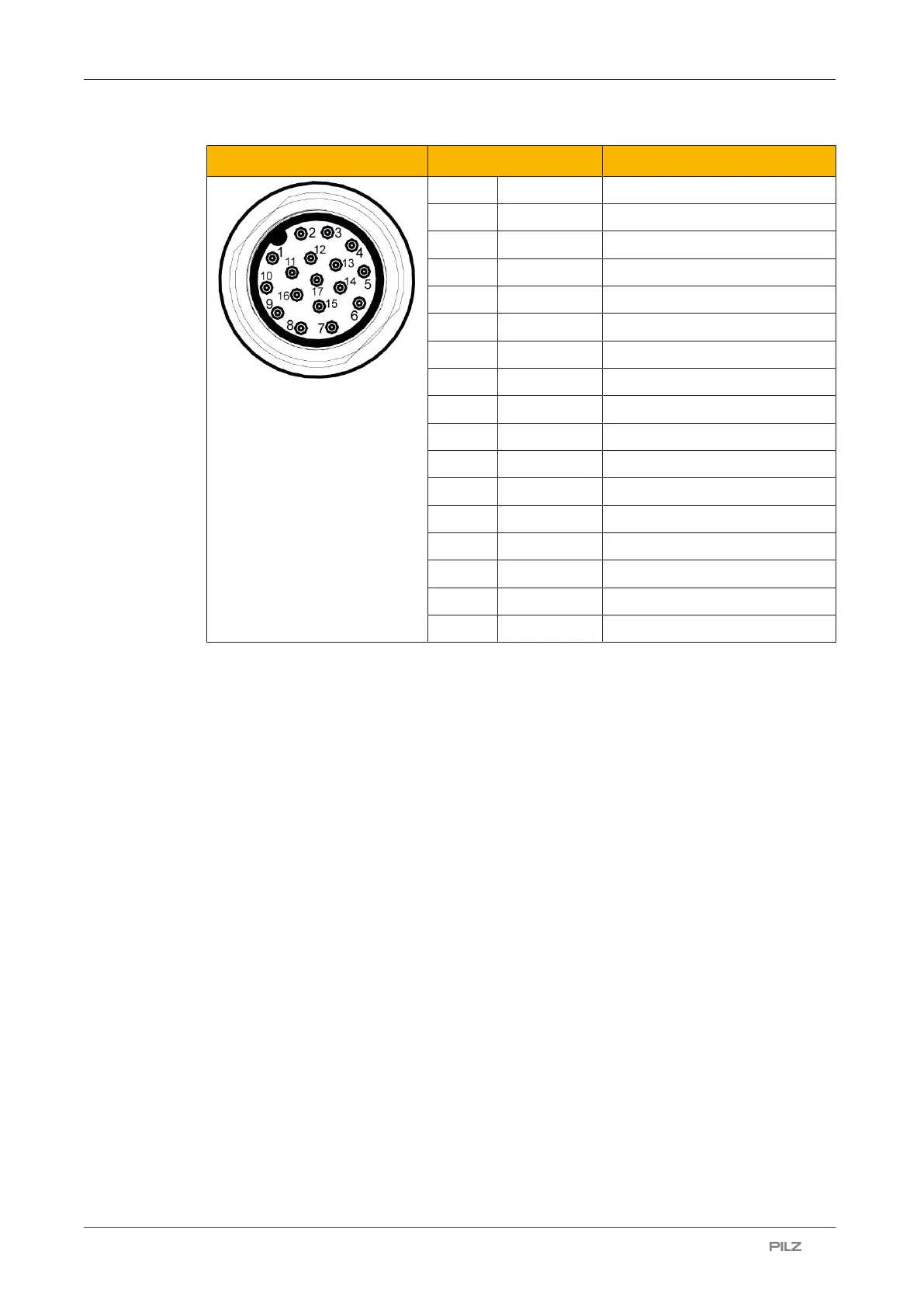
Male 17-pin connector Pin/colour Description
1 Brown 24VDC
10 Brown 24VDC
11 Brown 24 V DC
2 Blue 0VDC
3 Blue 0VDC
12 Blue 0VDC
14 White Configurable input
7 Black Configurable input
6 Orange Configurable input
17 Purple Configurable input
4 Green Configurable output
15 Yellow Configurable output
5 White/black Configurable input/output
9 Red Configurable input/output
13 Grey OSSD 11
8 Pink OSSD 12
16 Yellow/green Functional earth
The configurable inputs and outputs can be used for both input signals and output signals.
The configurable inputs can be used for all input signals.
} Restart and reset
} EDM (when using the 17-pin connection)
} Switching the monitoring of zone sets
} Dynamic and static muting
7.3 Connector pin assignment for subscriber unit
The subscriber unit of the safety laser scanner PSEN sc M 3.0/5.5 08-17 series has two
hinged 8-pin M12 sockets for connection to the master unit or to another subscriber unit. In
the PSENscanConfigurator, this configuration must also be made when creating a new
configuration.
} Two hinged 8-pin M12 sockets for connection to the master unit or a subscriber unit
– Two inputs on the socket to the master or an upstream subscriber unit
– Two outputs on the socket to the master or an upstream slave unit
– Two connections each for the supply voltage via the master unit and functional earth

 Loading...

