Installation and alignment
Operating Manual PSEN sc M 3.0/5.5 08-17
1005387-EN-05
| 79
8.6 Installation for inclination upwards and downwards
} The setting of the angle of inclination of the safety laser scanner is not changed when ex-
changing the safety laser scanner.
Prerequisites
} PSENscbracketP (see Order references [ 135])
} Mounting surface with 2 drill holes, 10mmdeep, distance 73mm horizontally to each
other for attaching the PSENscbracketP
} The protective bracket PSENscbracketH must already be attached to the safety laser
scanner (see Installation of the protective bracket PSEN sc bracket H on the safety laser
scanner [ 75]).
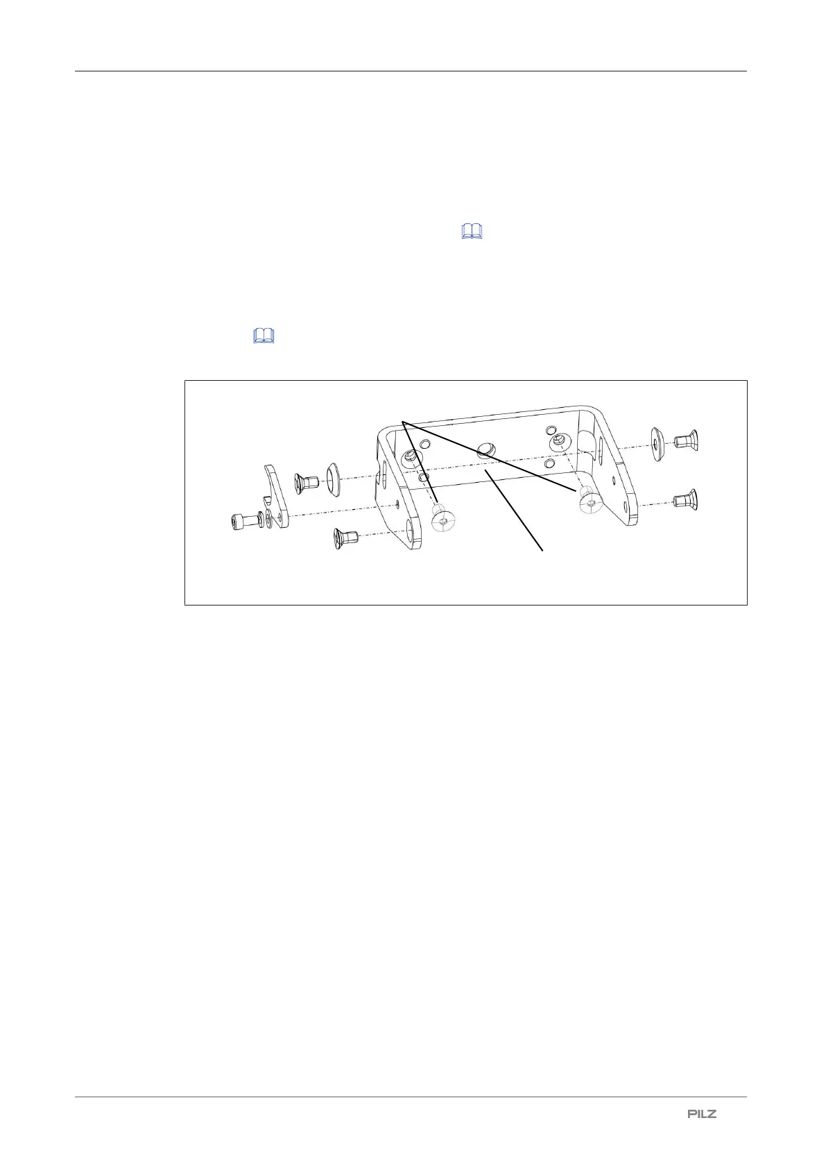
Procedure:
Legend
[1] Adjusting disc for angle of inclination
[2] Set screw for adjusting disc for angle of inclination
[3] Fixing screws for safety laser scanner
[4] Fine adjustment screws for the incline of the safety laser scanner
[5] PSEN sc bracket P
[6] Fixing screws for fixing to the mounting surface
Procedure:
1. Fix PSENscbracketP with the fixing screws [6] to the mounting surface and tighten
the fixing screws [6] alternately and evenly with 3 Nm.
2. Fix the adjusting disc for angle of inclination [1] with the set screws and washers [2] on
the PSENscbracketP (right or left).
3. Align the middle of the adjusting disc for angle of inclination [1] with the center of the fix-
ing for the safety laser scanner [3] and tighten the set screw for the adjusting disc for
angle of inclination [2] with 2,5 Nm.

 Loading...

