Installation and alignment
Operating Manual PSEN sc M 3.0/5.5 08-17
1005387-EN-05
| 76
8.4 Installation on the floor
Prerequisites
} The protective bracket PSENscbracketH must already be attached to the safety laser
scanner (see Installation of the protective bracket PSEN sc bracket H on the safety laser
scanner [ 75]).
} PSENscbracketP or PSENscbracketPR (see Order references [ 135])
Procedure:
[5]
[7]
[6]
[8]
[1]
[2]
[3]
[4]
[4]
[3]
[7]
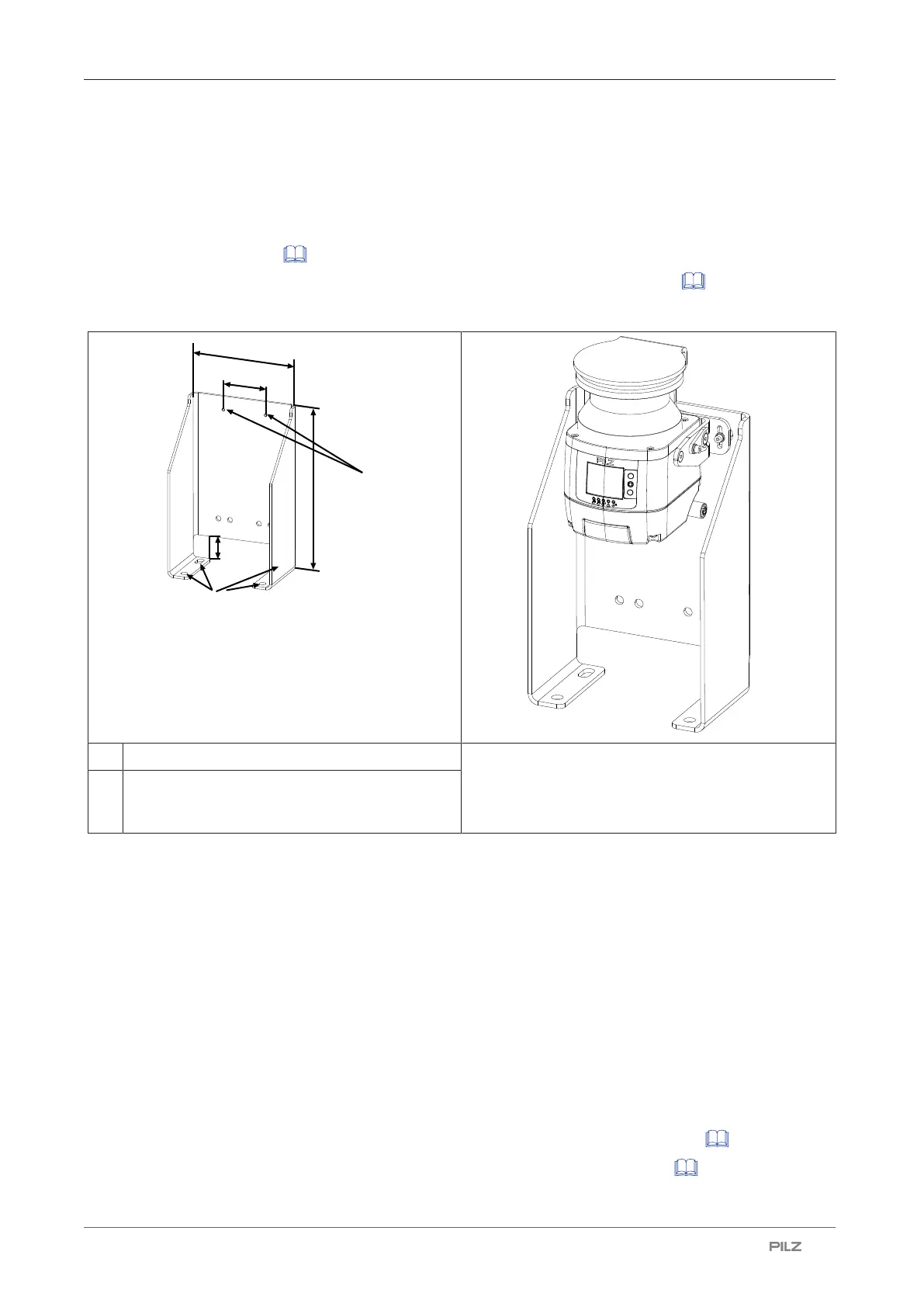
[1] Drill holes for attachment to floor PSEN sc with PSEN sc bracket installed on PSEN
sc bracket F
[2] Through holes for attaching the
PSENscbracketP or PSENscbracketPR to
PSENscbracketF
1. Fix PSENscbracketF with the fixing screws to the floor and tighten the fixing screws
alternately and evenly with 3 Nm.
2. Fix PSENscbracketPR or PSENscbracketP with the fixing screws to
PSENscbracketF and tighten the fixing screws alternately and evenly with 3 Nm.
3. Fix the adjusting disc for angle of inclination [1] with the set screws and washers [2] on
the PSENscbracketP (right or left).
4. Align the middle of the adjusting disc for angle of inclination [1] with the center of the fix-
ing for the safety laser scanner [3] and tighten the set screw for the adjusting disc for
angle of inclination [2] with 2,5 Nm.
5. Insert the safety laser scanner in PSENscbracketPR or PSENscbracketP with the
bracket PSENscbracketH to the top and fix the safety laser scanner with the screws
[3] and [4]. Tighten all four screws to 3 Nm.
6. Set the angle of inclination of the safety laser scanner, if necessary. [ 80]
7. Set the side inclination of the safety laser scanner, if necessary [ 80].

 Loading...

