Wiring
Operating Manual PSEN sc M 3.0/5.5 08-17
1005387-EN-05
| 70
4. Connect the supply voltage and the safety controller to the 17‑pin socket on the
memory module.
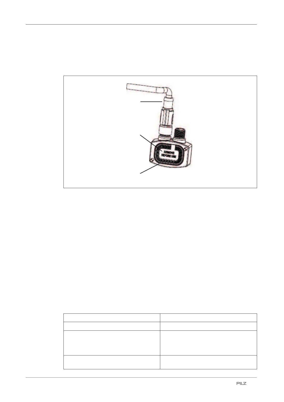
5. Remove the protective membrane [1] from the memory module and insert the memory
module at the safety laser scanner.
Legend
[1] Protective membrane
[2] Memory module
[3] Cable with connector
6. Screw the memory module with 1 Nm.
7. Place the protective cover at the safety laser scanner and screw the protective covers
with 1 Nm.
7.8 Connection to PSENscan Configurator
Note:
} Ensure that the software PSENscan Configurator is installed on the configuration PC.
We recommend that you always use the latest version (download from www.pilz.com)
} Ensure that the safety laser scanner is switched off when creating a connection to the
configuration PC.
100BaseTX cable
Bit rate 100 MBit/s
Max. segment length 100 m
Medium STP
(shielded twisted pair)
*1
2 pairs
Category 5
*2
Connection 4-pin M12 male connector /4-pin RJ45 male
connector

 Loading...

