Project configuration
Operating Manual PSEN sc M 3.0/5.5 08-17
1005387-EN-05
| 38
6.1.3 Horizontal application with automated guided vehicle systems
The following applies for these applications:
S = S
Br
+ (T
RtV
+ t
1
) * V
maxAGVS
+ Z
T
+ Z
R
+ Z
F
+ Z
B
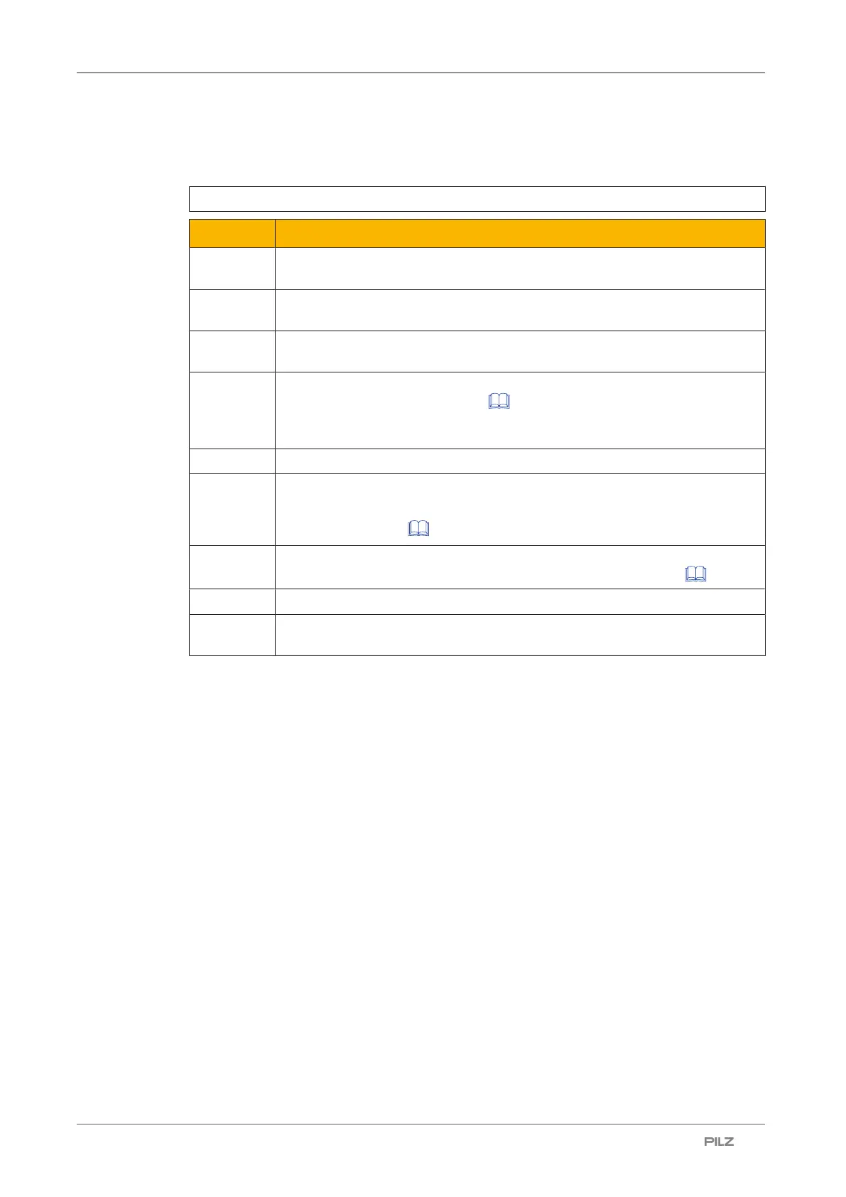
Icon Meaning
S Minimum distance in mm, measured from the start of the safety zone to the
danger source
S
Br
Braking distance of the automated guided vehicle system (AGVS) (see
Technical details of the AGVS)
T
RtV
Response time of the vehicle control system (see Technical details of the
vehicle control system)
t
1
Overall response time of the safety laser scanner in seconds (see Calcula-
tion of the overall response time [ 43])
Time between the violation of a safety zone and signal change at the OSSD
output on the safety laser scanner
V
maxAGVS
Max. approach speed of the automated guided vehicle system (AGVS)
Z
T
General safety allowance
Standard value in the calculation and the teach-in function = 100 mm, (see
distance from walls [ 51])
Z
R
Allowance when installing near intense light sources or reflective surfaces
(see Distance to intense light sources and to reflective surfaces [ 50])
Z
F
Allowance for missing ground clearance (length of a foot)
Z
B
Allowance for decreasing braking power of the automated guided vehicle
system (AGVS) in mm (10% of braking distance S
Br
)
Note:
} Height of the scan plane
Pilz recommends a scan plane height of 15cm.
A person lying on the floor is detected. A lower height would lead to reduced availability
because of the increased dust formation on the floor.
} If required, prevent access to dead zones on the sides of the automated guided vehicle
system through additional safeguards.
If this is not possible, the speed of the automated guided vehicle system must be limited
to 0.3m/s.

 Loading...

