Wiring
Operating Manual PSEN sc M 3.0/5.5 08-17
1005387-EN-05
| 64
7 Wiring
7.1 General guidelines
} Information given in the Technical details [ 127] must be followed.
} Do not lay the connecting cable near or in contact with cables that carry high or highly
volatile currents.
} Use separate cables to connect the wires to the OSSDs of different safety laser scanners
or safety switches.
} For supply voltage, use only PELV/SELV power supplies that have a voltage buffer in ac-
cordance with EN60204-1.
} The protection type (see Technical details [ 127]) can only be achieved by using the
Pilz connection leads available as an accessory.
} Connection to evaluation devices
– Use the cables listed in the order reference (see Order references for
accessories [ 135]) or equivalent cables.
– The terminals for connection to the evaluation device must be kept in a lockable con-
trol cabinet. This prevents unauthorised modifications.
} Ensure compliance with permissible cable bending radii (see Technical details [ 127]).
} Do not connect outputs with test pulses to the inputs on the safety laser scanner.
7.2 Connector assignment master unit
The safety laser scanner PSEN sc M 3.0/5.5 08-17 series has configurable inputs and out-
puts. In PSENscan Configurator these can be configured for the specific application.
The safety laser scanner PSEN sc M 3.0/5.5 08-17 series has an 8-pin male connector and
a 17-pin male connector.
The evaluation device, supply voltage and inputs are connected to the 17-pin male con-
nector.
The 8-pin male connector can also be used for further inputs. The selected use must be
specified in the PSENscan Configurator.
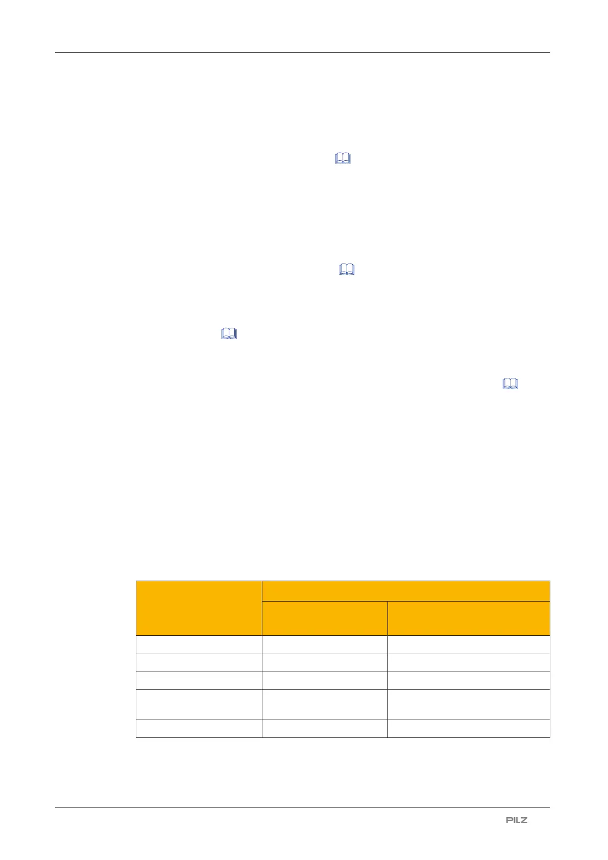
Max. number Connection to
17-pin male connector 8-pin male connector +
17-pin male connector
OSSD pairs 3 3
Configurable inputs 4 8
Configurable outputs 2 2
Configurable inputs/out-
puts
2 2
Zone sets 20 70

 Loading...

