2-6
PFC-6006 • 5403559 • REV D • 11/17
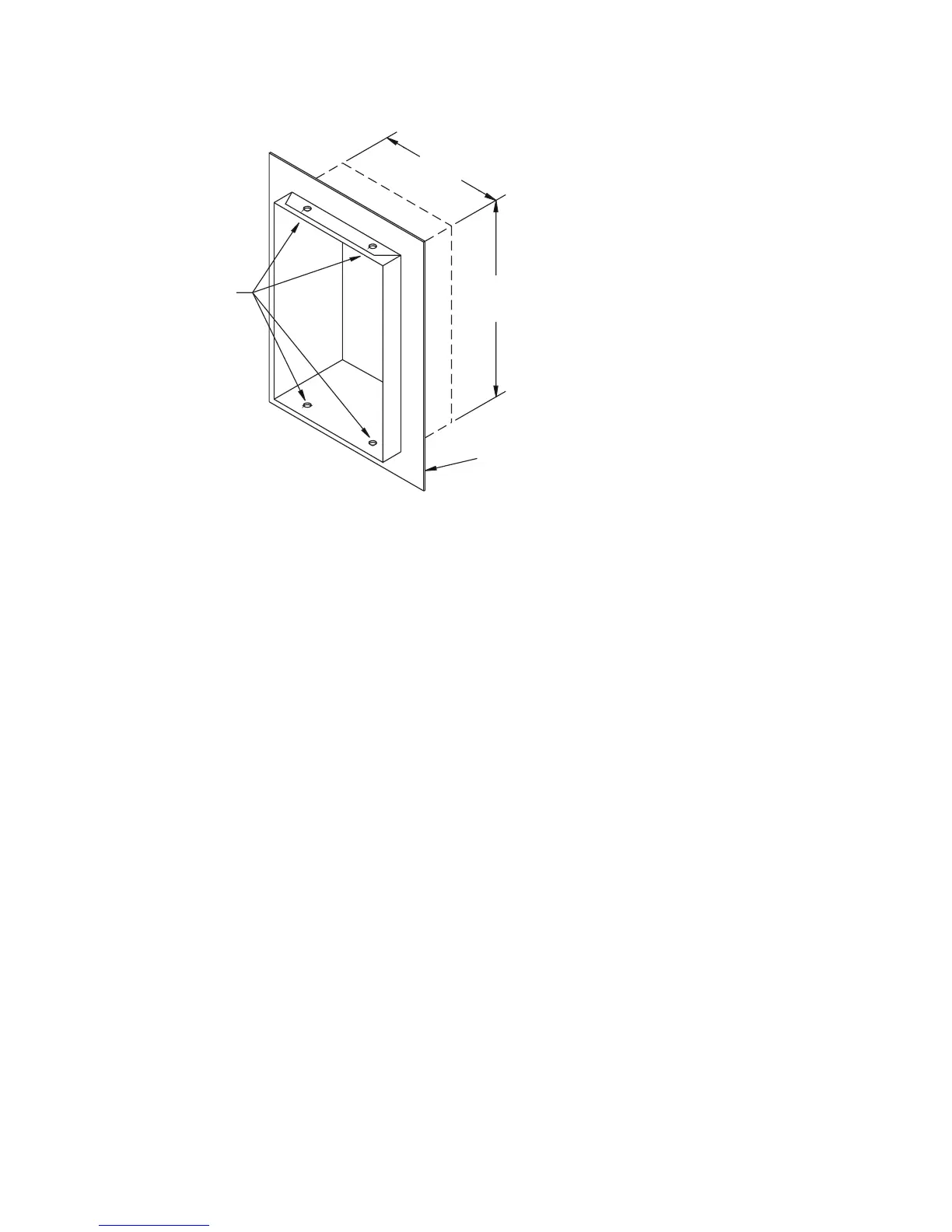
Figure 3. PFC-6006 Panel Showing Bezel Dimensions
Cabinet Mounting Instructions
To mount the cabinet:
1. The unit should be mounted in a convenient location, approximately 5 feet from the oor where it will be accessible for
testing and servicing.
2. The main circuit board module should be removed before attempting to mount the cabinet. Disconnect the AC power
from TB5. To remove the module, remove the two screws holding the chassis to the cabinet. Lift the module upwards,
approximately 1/2", in order to clear the cross-beam of the cabinet on which the module rests. Remove the module and set
aside.
3. The PFC unit may be surface mounted or semi-ush mounted using the optional trim bezel (refer to drawings shown earlier
in this section). For semi-ush installations mount the housing so that the front edge protrudes 1" from the nished wall
surface. After all conduits and wiring are in place and the wall surface is completely nished, slide the trim bezel in place and
fasten with 4 #6-32 x 1/4" machine screws and nuts.
4. Install all required conduits, external wiring and points and make all connections that are external to the panel. Replace the
module. With the AC power still turned off at the circuit breaker panel, connect the AC hot, neutral and ground wires to the
terminal block TB5 as shown in the "Cabinet Wiring Connections" drawing shown in this section.
5. Connect all the other wiring to the terminals as shown in the connection drawings. Turn the AC power on and connect the
standby batteries with the cable provided, polarity must be observed.
6. Replace false front panel and secure with mounting screws, taking care to not damage LED annunciator module cable.
7. Verify the operation of the complete system as outlined in the test procedure section.
(4) #6-32 X 1/4”
MACHINE SCREWS
AND NUTS
OPTIONAL TRIM
18 1/2”
14 1/4”
DWG# 3503-8
DWG #559-2