3-10
PFC-6006 • 5403559 • REV D • 11/17
Section 3: Installation
This section addresses installation procedures for Input Circuits 1–6, the NAC, the on-board DACT, and the optional RA-6075
or RA-6006 Remote Annunciator. Wiring requirements and conguration examples are included throughout this section. Please
read this section carefully before installing points and accessories to ensure proper installation.
Input Circuits
There are six (6) programmable Input or Initiating Device Circuits (IDC) provided on the PFC-6006, which are the same as
a conventional re system input. They are supervised, and power limited to protect 2-wire smoke detectors. Input Circuit #1
may be wired for either Class A, Style D or Class B, Style B; whereas Inputs #2-6 may be Class B, Style B only. All inputs are
suitable for automatic, manual, waterow or sprinkler supervisory service. (Please refer to the wiring examples located in this
section.)
Note: The panel has the intelligence to determine the applicable style for Input Circuit #1 based on the wiring
conguration used.
Input Wiring Specications
y Maximum short circuit current = 32mA.
y Maximum wiring resistance = 100 Ohms.
y Maximum wiring capacitance = 1 mF.
y Maximum wire length in feet = 100/Ohms per 1 ft. of wire.
y Normal standby current = 2.5 mA.
y Operating voltage range = 15.1VDC - 25.4VDC.
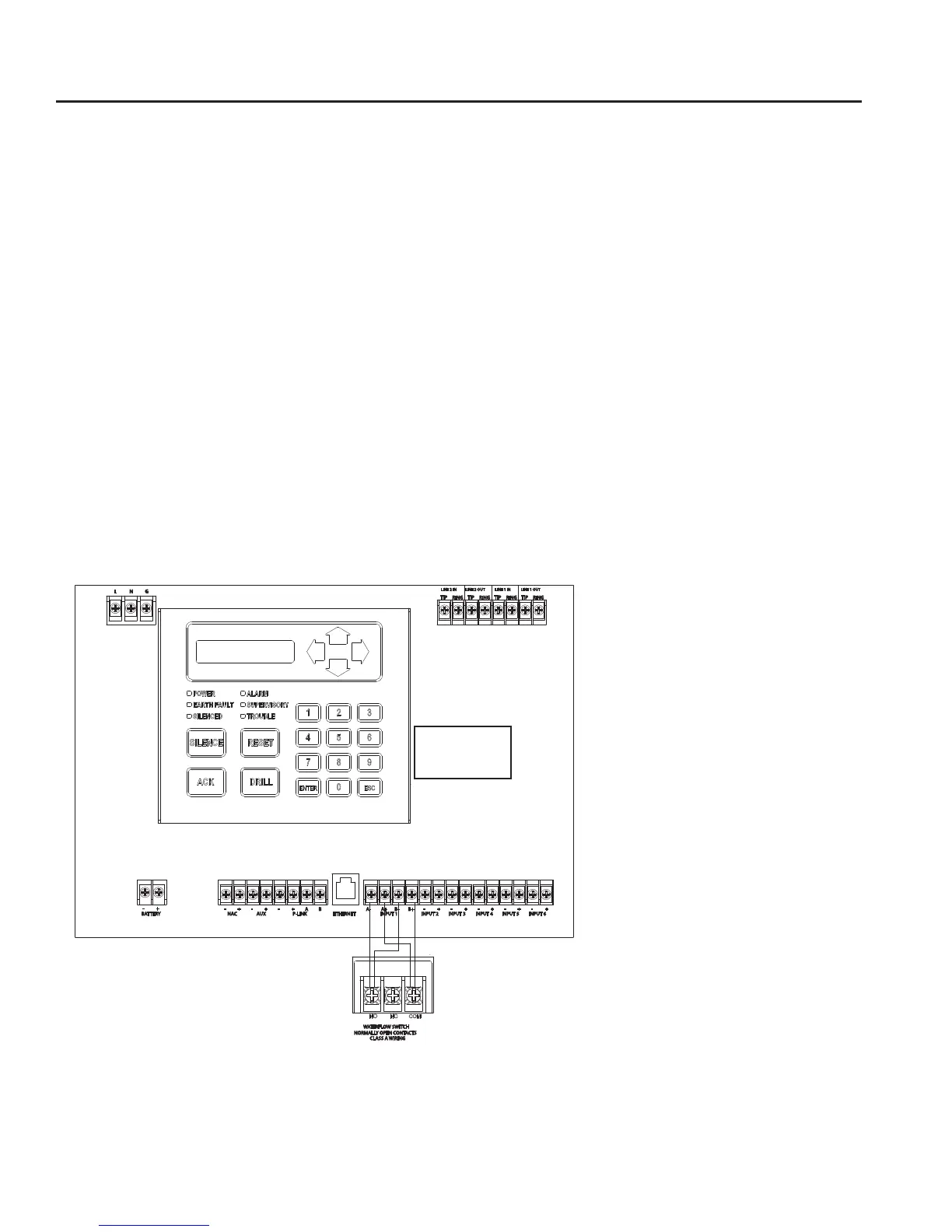
Input Circuit #1 Class A, Style D Wiring Conguration
Figure 7. Example of Input 1, Class A, Style D
Notes:
1. Input Circuit #1 may be wired as either Class A or Class B.
2. All other inputs are Class B only.
3. Maximum wiring resistance must not exceed 100 ohms.
4. The input has ground fault detection with 0 ohm impedance to ground.
5. The Potter part number for the listed end of line assembly is #3005013 EOL Resistor Assembly.
L N G
BATTERY
- +
NAC
- +
AUX
+-
P-LINK
+-
BA
ETHERNET INPUT 1
A- A+ B-
-
B+
-+ -+ -+ -+ +
INPUT 2 INPUT 3 INPUT 4 INPUT 5 INPUT 6
TIP
RING
TIP
RING
TIP
RING
TIP
RING
LINE 2 OUTLINE 2 IN LINE 1 OUTLINE 1 IN
WATERFLOW SWITCH
NORMALLY OPEN CONTACTS
PFC-6006
Input Circuit #1
Terminal Connection
DWG #559-4