2-8
PFC-6006 • 5403559 • REV D • 11/17
Battery Circuit Calculations
Before selecting the battery, it is important to determine the minimum size batteries for standby and alarm times desired for each
application. If the wrong batteries are installed in a specic application or incorrect current draw used, the proper standby and
minimum alarm time will not be present.
The battery circuit is rated for 8 to 18 AH batteries and swill operate the panel alarm for at least 24 hours and 5 minutes. The
cabinet will house up to two (2) 8 AH or two (2) 18 AH batteries.
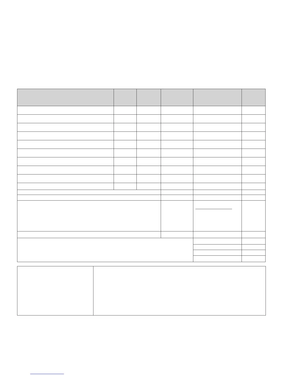
Please use the worksheet shown below to calculate the battery size and current draw required for each application:
Battery Calculation Worksheet
Description Quantity
Standby
(mA)
Total
Standby (mA)
Alarm
(mA)
Total
Alarm
(mA)
Main board (PFC-6006) 1 105 160
LCD Remote RA-6075 or RA-6006 20 25
Input Circuit #1
Input Circuit #2
Input Circuit #3
Input Circuit #4
Input Circuit #5
Input Circuit #6
NAC 1
Total (ma) Total (ma)
Convert to Amps x 0.001 Convert to Amps x 0.001
(*Refer to maximum allowable standby current) Total A: Total A:
Multiply by standby hours x____
60 minutes per hour
Alarm time (minutes)
Example:
5 minute alarm: enter 12
÷ ____
Total Standby AH Total Alarm AH
+Total Standby AH
Total AH
Efciency Factor ÷ 0.80
Required AH
*Maximum Allowable Standby Current
(UL 24-Hour standby time)
8 AH .265 A
18 AH .597 A
Important Notes:
1) FACP enclosure can house up to two (2) 18 AH batteries.
2) NFPA 72 requires 24 hours of standby power followed by 5 minutes of alarm activation.
3) Door holder circuits congured to disconnect upon AC loss need not be included in the
battery standby calculation since they will not draw power during that time. Door holders
will contribute to standby current draw when AC is present.
4) Total current must not exceed power supply rating (2A on PFC-6006).
5) LED/Relay current must be accounted for in the battery calculation for the supplying source.