5-24
PFC-6006 • 5403559 • REV D • 11/17
LEARN Programming
The LEARN mode enables you to efciently congure all connected, addressed Remote Annunciators. Only authorized users may
access this function. LEARN generates a list of all remote annunciators, which may be viewed on a remote computer.
(Refer to the “Conguring Points” and “Mapping Zones” sections for details.)
To run the LEARN mode:
1. From the control panel, press the Enter button to display the Main Menu.
• Press 6 to select Programming. The "Enter Code" prompt displays.
• Enter the user code as prompted.
• Press 2 to select LEARN. The "P-Link Initializing" prompt displays, and the system begins the initialization process.
2. Results are grouped by device type. If no changes are detected, the prompt “No changes” displays.
• Use down arrow to scroll through results by device type:
1=P-Link Found
2=P-Link Removed
Esc=Exit
• Select Esc when nished reviewing results. The system prompts to save or discard le.
3. Press 1 to save changes; press 2 to discard changes.
• If option 1 is selected, the “Accept conrmation” prompt displays.
• Press Enter to accept or Esc to discard.
4. Press Esc to exit programming menu.
Connecting the Computer and Panel
This section provides instructions on setting up connectivity between a laptop or networked computer and the control panel. Once
this is achieved, you may program your system using the panel conguration software.
Note: These instructions are relevant to all system congurations. If your PC connects directly to the panel, any
procedural differences are noted throughout.
Connecting a Computer to the Panel via a Network:
1. Connect cable to the Ethernet port on network (or directly to the panel if not using a network).
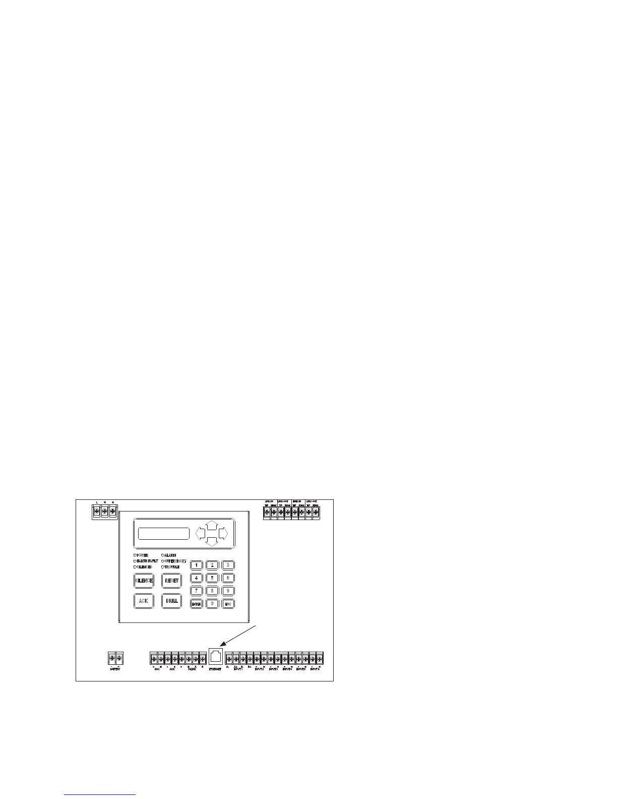
2. Connect Ethernet cable to port as shown below.
Figure 18. Control Panel Showing Ethernet Port
L N G
BATTERY
- +
NAC
- +
AUX
+-
P-LINK
+-
BA
ETHERNET INPUT 1
A- A+ B-
-
B+
-+ -+ -+ -+ +
INPUT 2 INPUT 3 INPUT 4 INPUT 5 INPUT 6
TIP
RING
TIP
RING
TIP
RING
TIP
RING
LINE 2 OUTLINE 2 IN LINE 1 OUTLINE 1 IN
Ethernet port
DWG #559-7