3-13
PFC-6006 • 5403559 • REV D • 11/17
P-Link Points
Accessory points, such as the RA-6075 or RA-6006 remote annunciator, are connected to the main control panel utilizing the
four-wire P-Link bus for power and communication. This panel supports a maximum of four (4) P-Link points, which can be
connected using a Class B, Style 4 wiring style.
Conguration Characteristics
y P-Link current rating may not exceed 0.5 amp based on the total between auxiliary and P-Link.
y P-Link maximum current is 500 mA.
y P-Link voltage rating is 24 VDC.
• Continuous DC frequency.
• P-Link circuit is supervised and power-limited.
Maximum Wire Resistance Formula (Wire Length)
The maximum resistance is based on the load placed on the circuit. To calculate the maximum wire resistance, use the following
formula:
(Total Annunciator Alarm Current) x (Wire Resistance) < 6 Volts
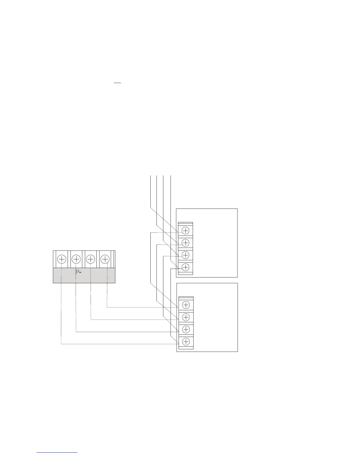
Figure 10. P-Link Device Class B Wiring Example
To the next device
- + A B
Expansion
Device
- + A B
P-LINK
- + A B
Panel
Connection
Expansion
Device
DWG #602-11A