2-9
PFC-6006 • 5403559 • REV D • 11/17
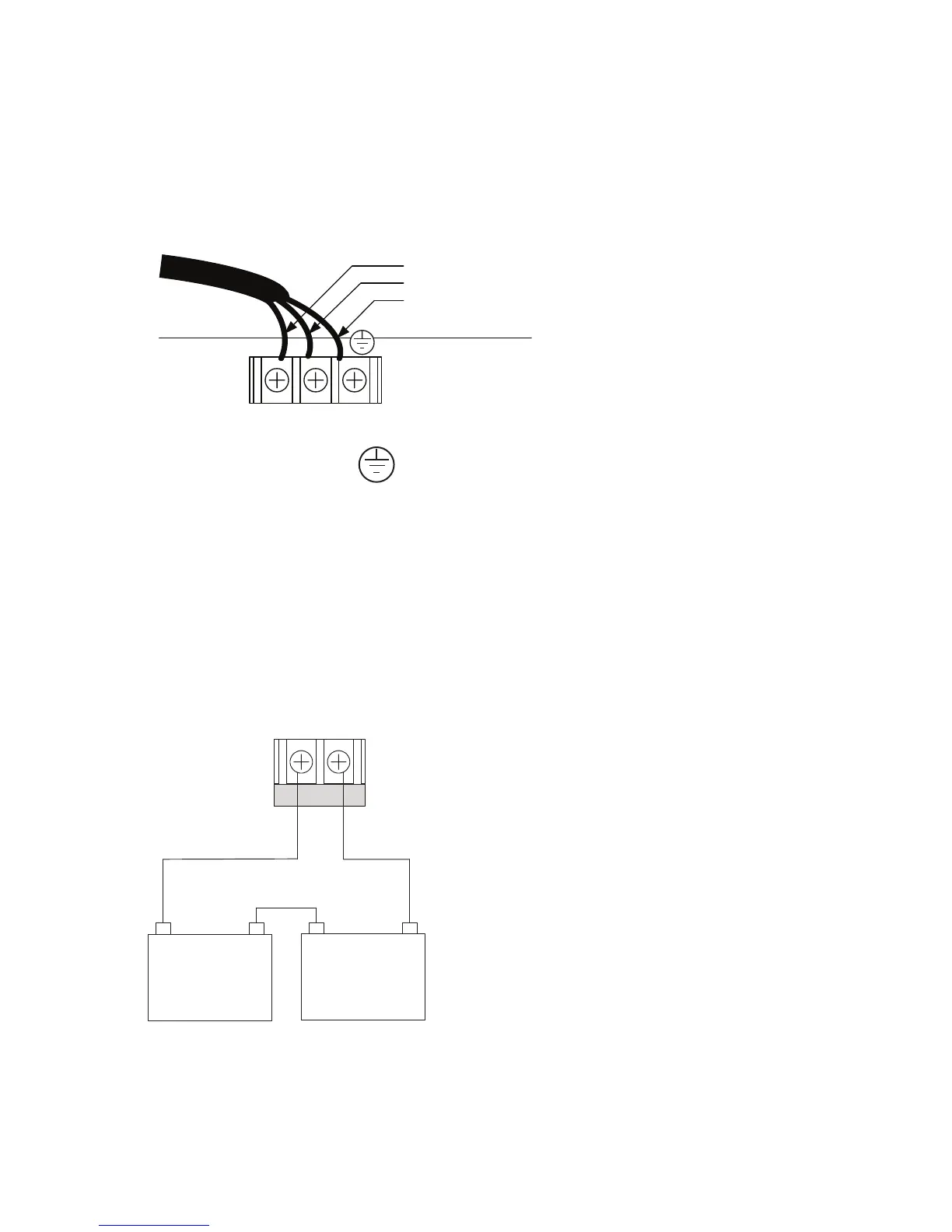
Main Supply Circuit
The AC terminals are located in the upper left hand portion of the main board. The main board supervises the main AC power and
provides indication that the AC power is absent. The terminals are rated at 120 VAC 60 Hertz and are marked so accordingly on
the board.
Figure 5. PFC-6006 AC Terminals
The earth ground connection is marked as “ " and is the furthest connection from the line voltage connection.
The AC input power rating is: Maximum of .75A at the nominal 120 VAC rating.
Battery Connections
The battery charging circuit is located on the main panel in the lower left portion of the board. The maximum battery charging
current is .5 amp DC; the charging voltage is approximately 27.3 VDC and is supervised.
Note: The battery should be clearly labeled as “Sealed Lead Acid Battery” or equivalent UL listed or UL Recognized.
Connect the battery wire leads to the terminal connections, as shown. Batteries should be replaced every ve (5) years or sooner
depending on annual testing.
Figure 6. PFC-6006 Battery Connections
Panel
Connections
BATTERY
-
+
12 V
Battery
-+
12 V
Battery
DWG #559-10
LN
AC POWER
Black
White
Ground
VAC 60 Hz
t to separate
switched AC circuit
Use 14 AWg wire or Heavier
with 600V Insulation