5-47
PFC-6006 • 5403559 • REV D • 11/17
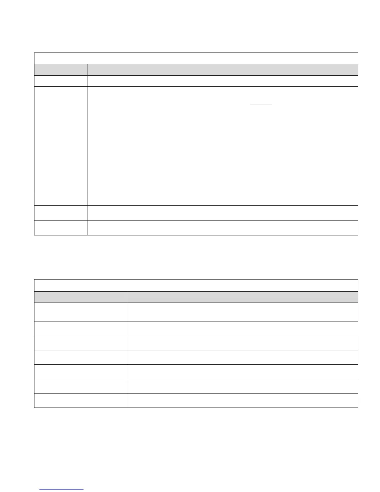
Mapping Terminology
The table below provides mapping terms that may be helpful to you in understanding the mapping concept:
Table 16: Mapping Terminology
Term Denition
Mapping
Creating relationships between points, modules and sensors and dening their behavior.
Zone
A group of points.
Zones may represent a group of points located in a specic physical area at the site.
Example: Zone 1 comprised of all alarm devices for a sprinkler system [i.e., pull station #1, one (1)
water ow device, and one (1) strobe-NAC].
Zones may represent a set of points congured for a specic function; their location may be scattered
throughout the site. This group is a “logical” grouping or zone.
Example: Zone 2 comprised of all points in Zone 1 as described above, plus a 2
nd
pull station located
at end of a hallway and two (2) additional smoke detectors.
Notes:
1. If all input / output points are grouped into one (1) zone, when any input is activated, all outputs
activate.
2. A device or point may be mapped into more than one (1) zone.
Point
Any specic initiating device circuit (IDC) or appliance connected to panel.
Latching
Device will not automatically reset; device must be RESET at the keypad to remove condition.
Non-Latching
Device will automatically reset when trouble and supervisory condition is no longer present.
Zone Types / Styles
You may dene or congure each zone to serve a specic purpose or to create specic output results. For procedures on how to
select Zone styles, refer to the “Conguring Zones” section of this manual. The following zone styles are available:
Table 17: Zone Styles
Zone Description
Alarm
•y Default zone type.
•y Sets system into an Alarm condition when any input is activated.
Supervisory
Used for all Supervisory inputs.
Auxiliary
Used for all “Aux” inputs.
Fire Drill
Comprised of input / output points that will activate when running a Fire Drill.
System Alarm
Used for outputs that will be activated upon any alarm.
System Supervisory
Used for outputs that will be activated upon any supervisory.
System Trouble
Used for outputs that will be activated upon any trouble.