2-3
PFC-6006 • 5403559 • REV D • 11/17
Electrical Specications
Please refer to the table below for electrical specications:
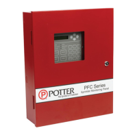
Table 3: System Panel Electrical Specications
Panel # NAC Rating per NAC Notes Style and Class
PFC-6006 1 NAC 0.5 Amp
Input Circuit 1 may be congured as Class A
or Class B; Inputs 2-6 as Class B only.
Inputs – Class A or B
NAC – Class B
P-Link – Class B
All are Low Voltage and
Power Limited
System Size Specications
Please refer to the table below for system size specications:
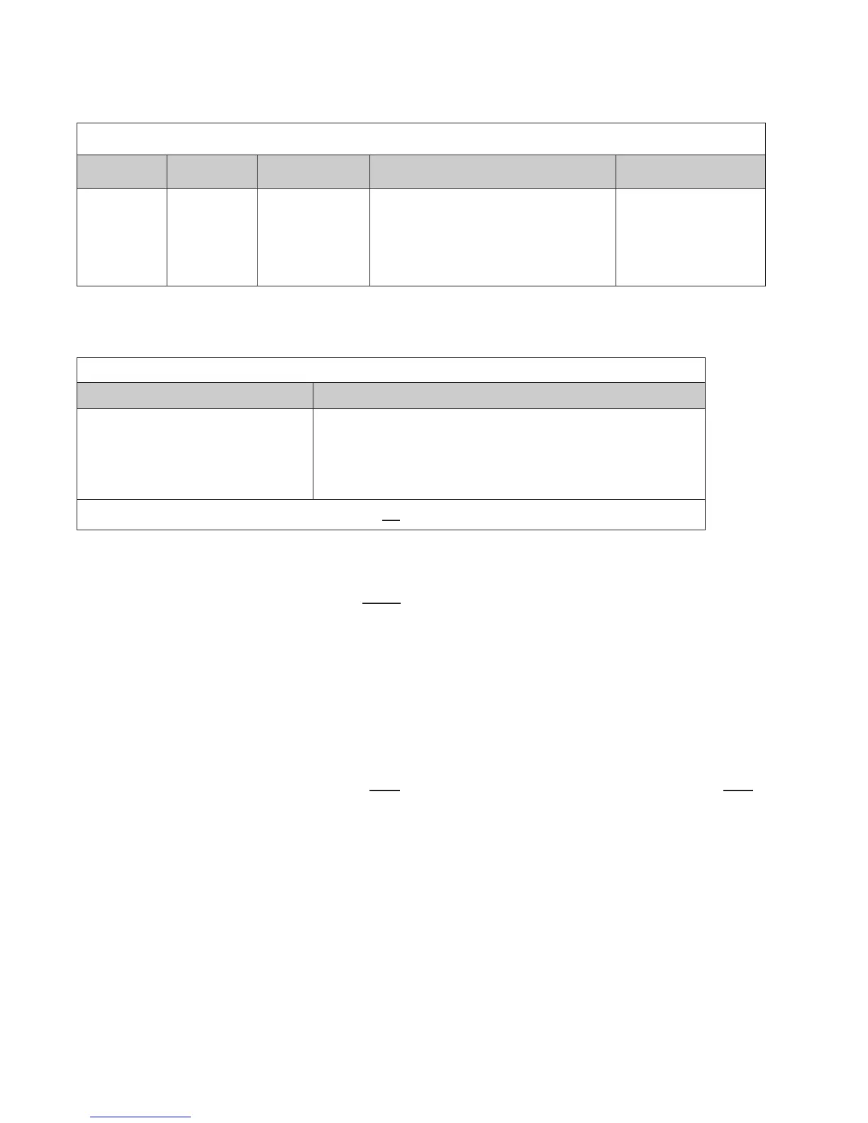
Table 4: System Size Specications
Accessories/Subassemblies Maximum System Size
PFC-6006
•y Six (6) input circuits on the main board
•y One (1) notication circuit on the main board
•y One (1) on-board DACT
•y One (1) auxiliary power output*
•y One (1) P-Link connection*
*Note: P-Link 24VDC and auxiliary power combined are not to exceed 0.5A.
Main Board Wiring Specications
There are several wiring requirements to consider before connecting circuits to the main board: (1) the circuit separation,
and (2) wiring types.
All wiring should be sized and installed to comply with NFPA 70, NFPA 72, and local codes and ordinances. For Canadian
installations, all panel wiring should be installed and maintained in accordance with CAN/ULC-S524M, (Standard for all
Installation of Fire Alarm Systems), all other applicable sections of the Canadian Electrical Code and any specic requirements of
the Authority Having Jurisdiction.
Circuit Separation
Proper separation between the different types of circuits must be maintained between Power Limited, Non-Power Limited, and
High Voltage wiring to reduce electrical interferences, transient voltage or voltage ratings.
y Separations between the different wiring types must be maintained by at least ¼ inch and the wire insulation must be for the
higher voltage.
y The control panel cabinet has sufcient knockouts located around the periphery allowing the installer to maintain separation
between power limited and non-power limited connections.