3-12
PFC-6006 • 5403559 • REV D • 11/17
Notication Appliance Circuits Installation
There is one (1) NAC circuit provided on the PFC-6006 rated as continuous 0.5 amps at 24 VDC. The NAC circuit is congurable
as Class B, Style Y only. (Please refer to the wiring example located in this section.)
NAC Wiring Characteristics
y Output is supervised and regulated.
y Circuit is power limited.
y Normal standby supervisory current is approximately 1.2 mA
y Low current trouble activation is 0.8 mA; High current trouble activation is 1.7 mA.
y Maximum RMS current is .5A.
Note: Type of NAC output is selectable, and may be congured for strobe synchronization with Potter/AMSECO®, Cooper
Wheelock®, Gentex®, or System Sensor® strobe points. Refer to the listing of compatible models located in the “NAC
Compatibility Document”, Potter #5403592, for this information.
NAC Maximum Wiring Impedance Formula
The maximum impedance is a function of the load placed on the circuit. To calculate the maximum line current impedance, use
the following formula:
(Alarm Current of Notication Appliance) x (Wire Resistance) < 1.2 Volts
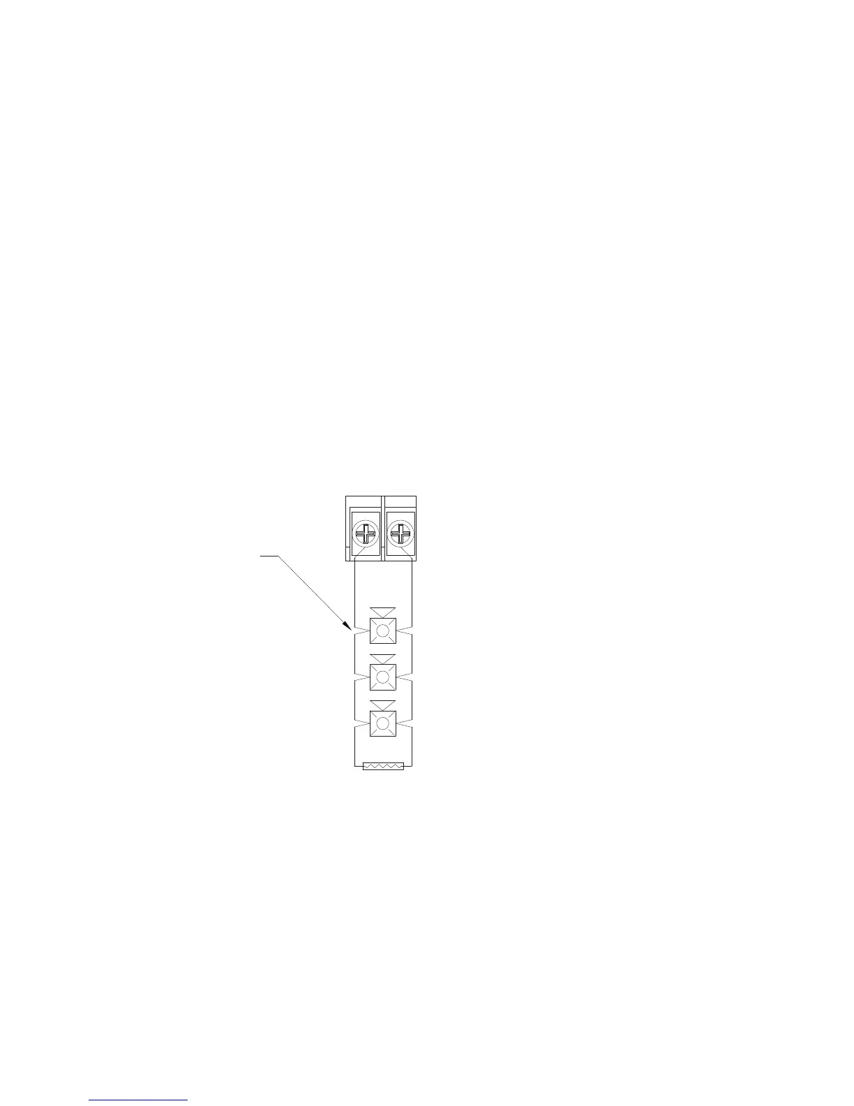
NAC Wiring Conguration
Figure 9. NAC Class B, Style Y Wiring Example
Notes:
1. The Potter part number for the listed end of line assembly is #3005013 EOL Resistor Assembly.
2. The panel has ground fault detection on the NAC circuit. The impedance to ground for ground fault detection is 0 ohms.
3. The 1.2 Volts is based on the worst case loading at the remote end of the NAC circuit (lump sum method). The total drop
of 1.2 Volts should be measured from the terminals to the most remote device.
DWG #559-6A
NAC
- +
Notification Appliances
5.1k EOL
Potter Part # 3005013
Note: the resistance of external wiring shall be determined using the following formula ---
(Alarm Current of Notification Appliance) x (Wire Resistance) < 1.2 Volts