Home
Preproofer
Printer
770
Page 41 (Prepare the BACK Printer)
Preproofer 770 - Prepare the BACK Printer; Remove Paper Roll Cover
126 pages
Manual
Save Page as PDF
To Next Page
To Next Page
To Previous Page
To Previous Page
Loading...
Prep
are the B
ACK Printer
Remove the Pape
r Roll Cover
6
Preproofer x700 / x900
–
HW
Installation Manual
6-1
PP x700/x900 v1.7
6
Pr
ep
are the BACK Print
er
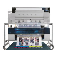
6.1
Remove th
e Paper Roll Cover
6.1.1
Roll Cov
er
Assembly
T
ake the screws off on both sides of the Paper R
oll
Cover
.
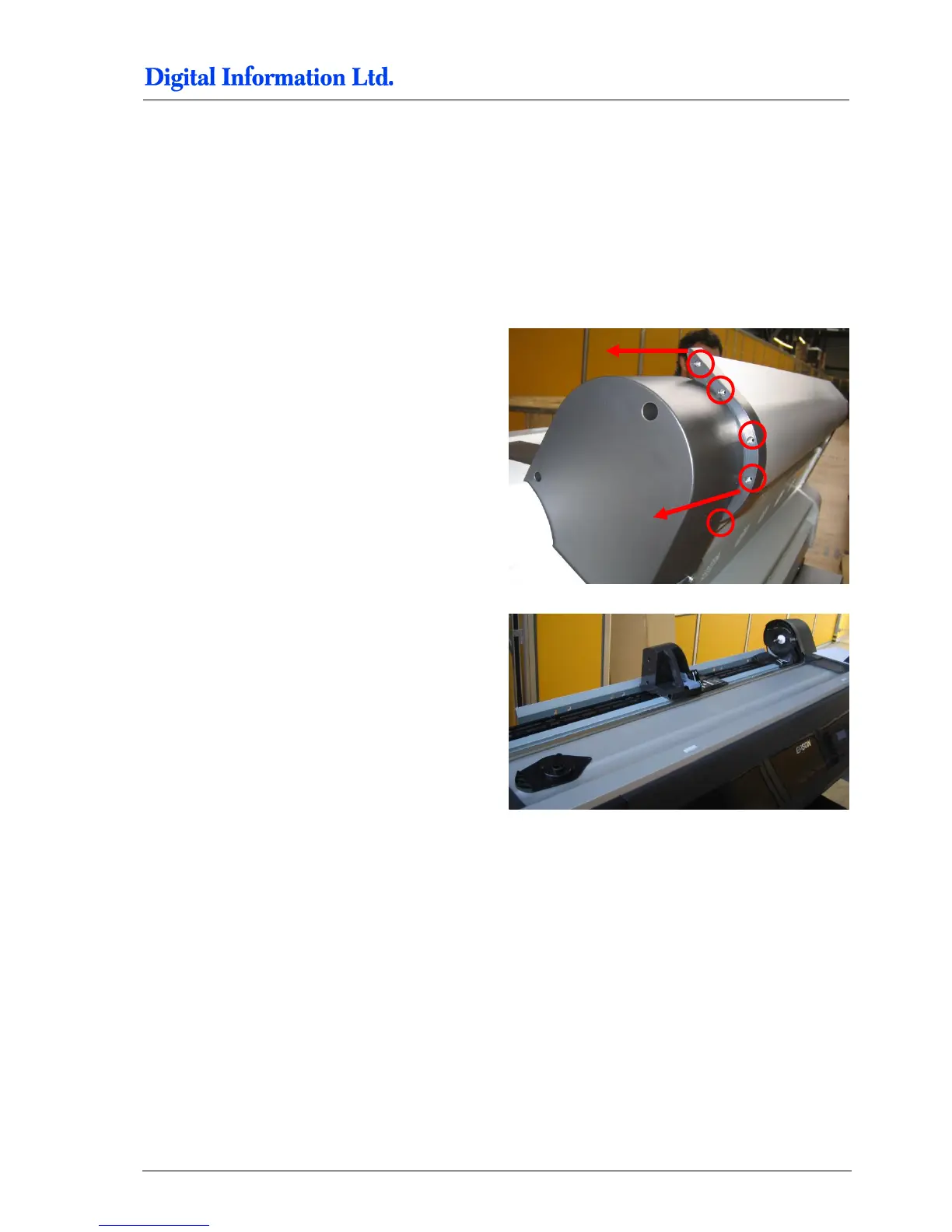
Now spread out the t
wo black plastic parts on both
sides to take off the aluminum
Paper Roll Cover
.
40
42
Table of Contents
Main Page
Default Chapter
3
Table of Contents
3
1 Introduction
7
2 Safety
9
Warning
9
3 Pre Installation Tasks
10
Tools Required for the Installation
10
PC Specification
10
Materials Required for Installation
10
Unpacking
11
4 Frame Setup
13
Overview
13
Frame Parts
14
5 Assembly
17
Frame Sides
17
Additional Parts
17
Mount the Base Plate for the Wheels
18
Mount the Pillar and Distance Profile
19
Mount Bracket to Frame Sides
21
Additional Parts
21
Mount the Brackets
22
Mount Cross Member Top
26
Cross Beams
27
Mount the Cross Beam for TOP Printer
27
Mount the Cross Beam for BOTTOM Printer
28
Mount the Stabilization Cross Beams
29
Tighten the Stabilization Cross Beams
31
Position the Cross Beam for BACK Printer
32
Position the Cross Beam for FRONT Printer
33
Brackets for Fixing the Printer to the Frame
35
Additional Parts
35
Mount Brackets to Profile
36
Mount the Cable Channel
37
Additional Parts
37
Add the Wheels
38
Additional Parts
38
Mount the Wheels
39
6 Prepare the BACK Printer
41
Remove the Paper Roll Cover
41
Roll Cover Assembly
41
Optional: Remove the Paper Roll
42
Take off the Screws
42
Remove the Roll Adapter Holder and Guide
42
Take off the Guide
42
Take of the Roll Paper Adapter
43
Mount the Base Profile for Paper Guide / Camera Holder
43
Additional Parts
43
Mount the Profile
44
Optional: Take off the Black Side Cover
45
Set the Wires
45
Additional Parts
45
Open PCB Cover on the Epson Printer
47
Cable from Electronic Box
47
CUT MOTOR Setup
48
Remove the CUT Motor Cable
48
PAPER FEED Motor Setup
49
Take off the Paper Feed Motor Cable
49
CUT MOTOR ENCODER Setup - Electronic Box - HW Release 2
51
Take off the End Switch and Encoder Cable
51
Take off and Reconnect the End Switch and Encoder Cable
51
Wire the Control Panel Back Printer
53
Remove the Control Panel
53
Solder the Wires to the Panel
53
Guide the Cable to the Electronic Box
55
7 Prepare the FRONT Printer
57
Wire the Control Panel Front Printer
57
Take off the Control Panel
57
Solder the Wires to the Panel
57
Guide the Cable to the Electronic Box
59
8 Set the Printers into the Stand
61
Additional Parts
61
Back Printer
62
Front Printer
64
9 Paper Guide / Camera System
65
Side Parts - Step 1
65
Parts Used
65
Assembly
66
Side Parts - Camera Holder BACK Printer
67
Parts Used
67
Assembly
68
Assembly „Right Holder" and „Camera Holder
69
Parts Used
69
Assembly
69
Assembly Camera Holder Front Printer
70
Parts Used
70
Assembly
71
Mount Side Holder Parts to BACK Printer
71
Additional Parts
71
Mount the Side Holders to Profile
72
Paper Guide Tubes
73
Additional Parts
73
Mount Paper Guide Tubes
74
Tube Stopper
75
Additional Parts
75
Mount Tube Stopper
76
Add Slot Nuts to Profile Front Printer
76
Additional Parts
76
Add Paper Guide and Paper Tension Parts
78
Additional Parts
78
Mount Paper Guide Tube Front Printer
79
Mount the Paper Tension Guide
80
Camera and Bar Light on Back Printer
81
Additional Parts
81
Mount Camera and LED Bar Light
83
Camera and Bar Light on Front Printer
83
Additional Parts
83
Mount LED Bar Light to Holder
84
Mount the Holder to Front Printer
84
Mount the Camera
85
Paper Bow for Back Printer
85
Additional Parts
85
Assembly
86
Assembly to the Profile
87
Paper Bow for Front Printer
87
Additional Parts
87
Mount the Electronic Box
89
Align the Printers
89
Paper Path
89
Parallel Alignment Front Printer
91
Parallel Alignment Back Printer
94
Horizontal Alignment
95
10 Printer Panel Configuration
96
Parameter Setup TOP and BOTTOM Printer
96
TOP Printer - Configure Custom Paper 1
97
Bottom Printer- Configure Custom Paper 1
101
11 LED Bar Light
107
Power Supply Setup for LED Bar Light
107
12 Setup Electronic Box - HW Revision 2 - Nov 2011
109
HW Changes
109
Power Supply Setup for Electronic Box
109
Setup the Lantronix Device
110
Run the Test Program
110
Calibrate the CUT Motor Parameter
112
Calibration - Step by Step
112
Setup Motor Speed
115
13 Setup Electronic Box - HW Revision 1 - OLD STYLE
116
Power Supply Setup for Electronic Box
116
Setup the Lantronix Device
117
Run the Test Program
117
Setup the CUT Parameters
118
14 Test Printer Panel Cable Connection
121
Test „Paper down BACK
121
Test „Pause BACK
121
Test „Pause FRONT
122
Test Paper MOVE
122
15 Calibrate Paper Movement Printer Back
123
Background
123
Paper Traction Calibration
123