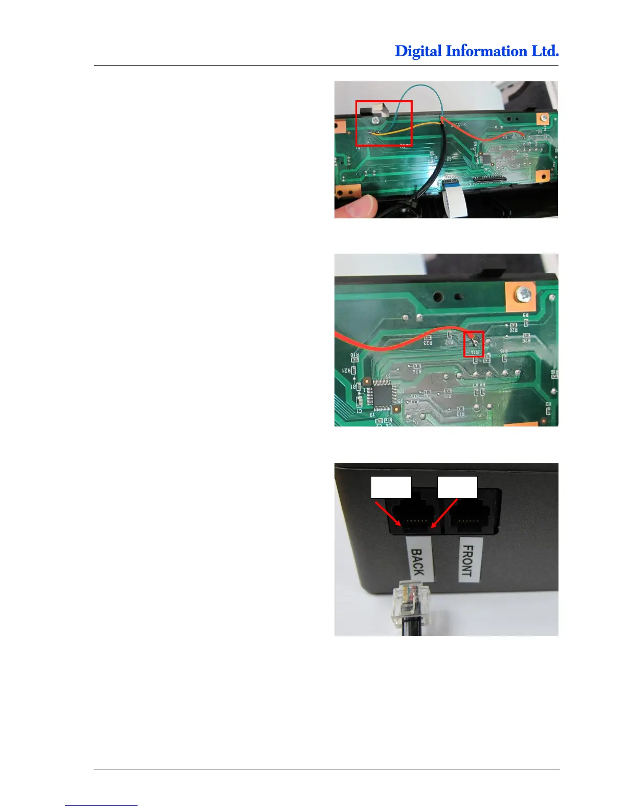
Locate the solder points for GROUND and PAUSE.
Thick conducting path is GROUND, thin path is
PAUSE.
On the picture to the right, the cables are:
YELLOW = PAUSE
GREEN = GROUND
Locate the solder point for “PAPER FEED DOWN”.
On the picture to the right, the cables are:
RED = PAPER FEED DOWN
Check with the delivered cable (RJ11 connector at
one end) the correct cable assignment and solder
the wires to the panel.
For the BACK Printer, the pins are located like
Pin 3 = PAPER FEED DOWN
Pin 4 = GROUND
Pin 5 = PAUSE
For the FRONT Printer assignment, see chapter
7.1.2