2-6
VIBXPERT II 05.2012
Getting started - Interfaces
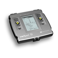
Digital
The yellow channel is used as the:
- Input for digital signals from a trigger or a RPM sensor
- Serialinterfacefordatatransmission(RS232)
- Output for the analog signal (connection for headphone/oscillo-
scope)
- Outputforstroboscopecontrol(TTLsignal)
The permissible range for trigger signals is:
-26V...0V(negative)or-5V...+26V(positive).
Switchingthresholdpositive: max.2.5Vrising
min.0.6Vfalling
Switchingthresholdnegative: min.-8Vrising
max. -10V falling
The input signal must not exceed the switching threshold of the
positive and negative range as otherwise incorrect measurements
can occur.
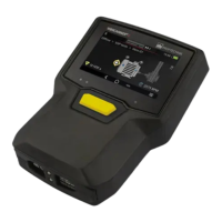
Temperature
This interface is used for the connection of a thermo couple type K.
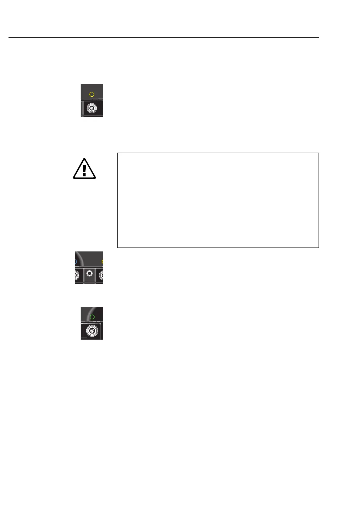
Communication
The green channel is used as the:
- Communication interface to the PC. The connection is established
viaanetwork(Ethernet)ordirectlyviaaUSBcable.
- USBprinterport.
- ConnectioninterfaceforanUSBpendrive.
Thenetworkisconguredinthe'DeviceSetup'(see'Ethernet'onpage
2-34).
Attention!

 Loading...