Do you have a question about the PRÜFTECHNIK VIBXPERT II and is the answer not in the manual?
Provides crucial safety instructions and guidance for operating the device correctly and safely.
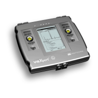
Details connections for sensors and data cables on the device front, with color-coded identification.
Explains the device is powered by a Lithium-Ion battery, with the battery icon indicating residual charge.
Details the standard 2 GB CompactFlash card and its replacement with higher capacity cards.
Guides checking and changing fundamental device settings before measurements, accessed from the start screen.
Explains settings for 'Route' and 'Template' modes, including route display type and graphic route options.
Configures autostart measurement, autostart MUX, route optimizer, and multi-task time optimization.
Configures 'AutoSave' for automatic result saving and sets conditions for stopping AutoSave.
Accesses the transducer menu for sensor pre-setting and configuration, allowing preselection of available transducers.
Allows checking and editing of measurement quantity, signal type, input range, accuracy, sensitivity, and offset.
Guides adding new transducers by entering name and setting parameters, then saving.
Explains enabling modules by entering a password, often found on a registration certificate.
Device must be registered in OMNITREND using PC license password for data exchange.
Provides access to service, maintenance, and training functions like Device Info and Offset Compensation.
Allows formatting, checking, and repairing the memory card. Formatting deletes all data.
Describes data transfer between VIBXPERT and PC via direct or network connections.
Guides connecting VIBXPERT to a network, setting IP address, subnet mask, and gateway.
Explains downloading and installing current device software from the PRÜFTECHNIK homepage using the update tool.
Defines a dataset for measurement: quantity, sensor, evaluation, and RPM requirements.
Activates Multimode mode. Tasks grouped into Overall Values, Signals, and Advanced tabs.
Saves measurement results after completion via MENU -> 'Save'. Enter file name.
Processes measurement tasks for regular schedules, compiled using OMNITREND.
Guides selecting a route, measurement location, task, connecting sensor, and starting measurement.
Details MENU functions like Skip/Unskip, Event/Comment, Delete result, Set unmeasured, Reset RPM, Break multitask.
Details MENU functions in the task selection screen: Skip/Unskip, Event/Comment, Multitask breakdown, Diagnostic Task, Task Manager, Display result, Delete result.
Uses 'Machine template' for measurements on identical machines with consistent locations and tasks.
Guides selecting a template, entering machine details, and starting measurement. Info field shows template load and last measurement dates.
Covers options for aborting, repeating, saving results, and changing measurement channel or sensor.
Confirms saving results after measurement. Can append or overwrite existing data.
Highlight measurement type, press F key, and select required measurement task from the list.
Guides creation of new tasks via 'Task Manager': enter name, change channel, select setups for measurement, sensor, evaluation, RPM.
Explains creating new setups for measurement, evaluation, or RPM for user-defined tasks via 'Task Manager'.
Covers measurement quantity, sample frequency, measurement time, frequency range, averaging type, overlap, and time-synchronous averaging.
Sets trigger type, level (as % of max range), and start time for measurements, controlling signal recording start/end.
Details measurement tasks in 'Signals' tab: Filter Type, HP/LP Filter, Demodulation factor, and frequency ranges.
Describes sensor parameter setup. 'Sensor Setup' menu is deactivated if a default sensor is defined.
Sets thresholds for overall value measurements or creates user-defined setups. Includes description entry.
Monitors machine conditions by recording overall values over time to trace condition and predict future development.
Accesses historical data in 'Route' mode for comparison with current measurements and trend display.
Starts a trend by opening a file in 'File manager', clicking the trend file, and appending the current result.
Compares current measurement with historical or reference data using OMNITREND data and 'Standard' display mode.
Warns if current value deviates significantly from historical. Green LED and R! symbol appear if deviation exceeds set limit.
Performs tasks at near locations simultaneously for faster route collection. Requires 2-channel module.
Supports triax sensors for X/Y/Z vibration recording. Requires special cable adapter for 2-channel devices.
Performs measurements based on time or speed, useful for recording values under specific conditions.
Records time waveforms over long periods. Checks settings for time and scan rate in task manager.
Uses 'Multiplexer measurement' for automatic data acquisition at many locations, processed within a route or template.
Conducts diagnostic measurements using multiplexer locations for vibration, FFT, Orbit, and RPM-dependent tasks.
Ensures measurement validity and no errors before evaluation. Displays task, channel, range, sensor, date/time.
Displays up to two overall values with RPM. Shows exceeded thresholds and corresponding LEDs.
Displays results as a trend curve if >2 measurements saved. Markers indicate individual measurements with details.
Displays results as XY diagram. Lower half lists highest amplitudes. Shows delta if thresholds exceeded.
Calculates characteristic overall values from signal (max/min amplitude, mean, p-p, RMS, Crest factor) via MENU.
Calculates spectrum from time waveform. Sets parameters: input signal, averaging mode, and window type.
Determines time waveform synchronously with rotation to emphasize RPM events and suppress stochastic results.
Displays spectrum in upper pane, time waveform in lower. Info options: Max 10, Alarms, Frequency marker, Trending values.
TrendingSpectrum shows waveform, spectrum, and up to 30 overall values based on OMNITREND frequency bands.
Compares trending values with reference values, showing a table with values and limits.
Compares trending values with historical data, displaying a diagram with trends.
Alters measurement quantity in spectrum (e.g., velocity to displacement). 'Alarms' function available only with original quantity.
Compares current spectrum with reference or historical spectrum, displayed in a 'waterfall' diagram.
Displays multiple spectra (up to 75) in a 3D waterfall diagram for analysis. Allows navigation and view changes.
Displays sound spectrum by breaking acoustic signals into frequency bands. Quantifies sound pressure level per band and overall.
Guides configuration of result display after measurement, accessing 'Display Setup' via MENU.
Sets zoom, cursor type, graph type (continuous/poles), axis labels, amplitude scaling, and default display mode.
Configures display for Coastdown (overall value, plot type), Orbit (polar/Cartesian), and Phase (continuous phase, speed marker).
Sets phase trend display based on time or RPM. Options to show result details, change diagram type, or show specific channels.
Configures spectrum display for 2-channel tasks, choosing spectrum only or including additional info. Sets display for channel A/B.
Chooses whether impact test results are displayed as time waveform or spectrum. Result selection dialog opens automatically.
Enables printouts of screenshots, reports, and route/template reports to USB printer or as PDF.
Creates detailed documentation including results, general info, and measurement details. Available for Spectrum, Time waveform, etc.
Defines report content by setting Company, Logo, Customer, Inspector/Asset, Result file name, Report event, and Setup info.
Prints reports for routes/templates, including overall values, trend parameters, visual inspection, and phase measurements.
Exports data (overall value, FFT spectrum, balancing, waveform, etc.) to MS Excel format via VIBXPERT Utility Program.
Assesses machine/bearing/gear conditions using RMS velocity and ISO 10816-3 standards. Includes peak values and crest factor.
Measures bearing condition using 'Carpet value' (lubrication) and 'Maximum value' (damage).
Uses Laser-Trigger Sensor for RPM measurement and trigger encoder. Detects signals optically from rotating shaft.
Uses thermocouple Type K sensors (handheld probe or magnetic sensor) for temperature measurements.
Records vibration changes during startup/shutdown to determine resonance frequencies. Available as Phase-RPM, Spectra-RPM, Overall Value-RPM.
Records overall vibration values relative to RPM. Resonance points indicated by RPMs with increased vibration amplitudes.
Records spectra while machine RPM changes, tracking RPM-dependent vibration components to identify resonance points.
Records phase amplitude and angle versus RPM. Resonance points indicated by increased amplitude and 180° phase jump.
Differences in displaying results of two-channel measurements. Spectrum-RPM shows one spectrum per channel.
Number of saved values affects result quality. 'Overlap' increases rate; 'RPM deviation' can reduce rate to save space.
Records shaft axis movement in journal bearing during runup/cooldown to identify fault conditions like oil whip.
Identifies faults causing spectral lines at same position (e.g., unbalance) using synchronous phase measurement.
Records shaft axis movement at constant speed using two non-contact sensors at 90° angular distance.
Detects periodic impacts in vibration signal, mainly for bearing/gearing damage diagnosis.
Spectrum of a spectrum, suitable for detecting regular structures in frequency spectrum, e.g., bearing/gearing damage.
Allows free definition of measurement quantities like voltage or current, recorded as overall value, time waveform, or spectrum.
Combines similar measurement tasks to shorten time, performing one signal measurement and calculating individual task results.
Tasks created in Task Manager. Set start measurement consecutively or simultaneously, define trigger channel.
Carries out vibration measurements (value, spectrum, time signal) on both channels simultaneously.
Determines structure resonance frequency and RPM ranges amplified by resonance.
Visualizes dynamic behavior of a structure and detects operating-critical natural vibration forms.
Measurement template for route mode, collecting data faster. Generates spectrum and up to 30 overall values from time signal.
Records and displays frequencies as multiples of shaft rotational frequency (= order). RPM is recorded simultaneously.
Converts frequencies to orders. RPM measured or entered. Advantageous for machines running at different RPMs.
Records DC component in signal for time waveform, spectrum, phase, coastdown, and orbit measurements.
Tool for firmware updates, saving/restoring results/settings, formatting card, exporting results, and file conversion.
Establishes data transmission via network or USB. Includes connection testing and IP address entry for Ethernet.
A vibration measurement system using coded points for identification of measurement locations on machines.
Never use sensor directly on machine surface; it must be locked onto the measuring pin. Ensure secure connection for reproducibility.
Provides information on treating VIBXPERT as a precision instrument, including storage, cleaning, and maintenance.
Provides detailed specifications for input channels, measurement parameters, computer, display, memory, interfaces, and power supply.
Addresses VIBXPERT not starting up due to flash memory failure, recommending firmware reloading.
Guides reloading firmware using VIBXPERT update tool, serial/Ethernet cables, and PC setup.
Details available firmware modules (Basic, 1-channel, 2-channels, Modal analysis, Recording, Balancing) and their features.
| Weight | 1.5 kg |
|---|---|
| Channels | 2 |
| Sampling Rate | up to 51.2 kHz |
| Display Type | LCD |
| Protection Class | IP 65 |
| Weight (approx.) | 1.5 kg |
| Display | Color display |
| Data Storage | Internal memory |
| Frequency Range (kHz) | 0.5 to 20 kHz |
| A/D Resolution | 24-bit |
| Memory | 4 GB |
| Operating Temperature | -10°C to +50°C |
| Data Transfer | USB |
| Storage Temperature | -20°C to +60°C |