4000-SERIES INSTALLATION, OPERATION AND SERVICE MANUAL
96 of 154
Table 32: Factory Preset Schedule on TH8110 Thermostat
19.13.3 BMS-Ready Control Option
The BMS-ready option provides inputs to receive
control signals from a customer determined control
system. Each BMS input is capable of receiving a
4-20mA or 0 - 10VDC from the control system. On all
air handlers, the burner modulation will be controlled
by the control system. For AM/VAV style air handlers,
the control system can also control the modulating
damper.
On DDC/BMS-ready systems, no temperature control
amplifier is installed. Discharge temperature
monitoring and modulation valve adjustment are
completed by the customer supplied control system.
For optimum efficiency, Rapid Engineering LLC
suggests to limit the discharge temperature to 160 °F.
19.14 Basic Air Handler Sequence of Operation
While the control transformer is energized, the
secondary side supplies 115 VAC to the control
circuit. When the fan switch is in the "on" position, the
M1 motor starter is energized and starts the blower
motor. The M1 motor starter auxiliary contact
supplies voltage to the burner switch and "Fan On"
light. When the burner switch is in the "on"/"winter"
position, power is supplied to the flame control
modu
le and the burner control circuit. The burner
control circuit includes the high temperature limit
switch and the low and high airflow pressure
switches. Once the burner control circuit is satisfied,
then the flame control module will execute the burner
ignition sequence. Once the pilot flame is ignited and
sensed by the UV scanner, the flame control module
will open the safety shutoff valve to ignite the main
flame. When the safety shutoff is opened, 115 VAC is
applied to the "Burner On" light and T3 transformer,
the secondary side supplies 24 VAC to the
temperature control amplifier. The temperature
control amplifier controls the modulating valve based
on the discharge temperature monitor (and also the
room temperature monitor, in the case of a DTC
remote panel).
19.14.1 Flame Control
Yo ur Rapid
®
direct fired air handler will be equipped
with either a Fireye
®
or Honeywell
®
brand flame
control.
The flame control is a safety device and not
serviceable. See Pages 51 through 53 for detailed
sequence of operation.
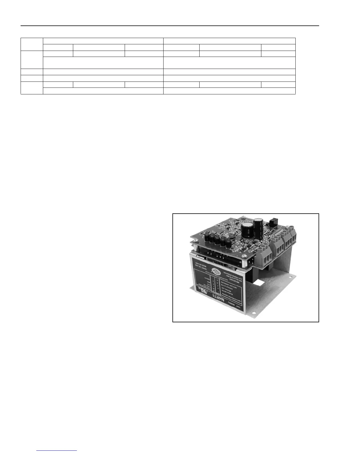
19.14.2 Fireye
®
M4RT1 Flame Safeguard
This control is located in the center of the main
control panel. To reset this flame relay, power to it
must be shut off and turned back on.
FIGURE 69: Fireye
®
M4RT1
This is an exposed circuit board one piece control. It
contains a fuse to protect itself from external shorts
or overloads and on its exterior it has five lights which
indicate the operating status of the control.
The functions of the indicator lights, which are
located on the programmer module, are as follows.
They are listed in the order you will find them on the
flame safeguard and is also the order in which they
will occur in the sequence. The indicators are
actually a red colored light emitting diode or LED, this
is how they will be referred to from now on.
Monday - Friday Saturday - Sunday
Time Temperature Fan Setting Time Temperature Fan Setting
Wake
6:00 AM 68° F Fan On 6:00 AM 62° F Fan Auto
The air handler will run continuously.
Temperature controlled by Maxitrol stat.
The air handler will run when the thermostat calls for heat.
Leave Unused Unused
Return Unused Unused
Sleep
5:00 PM 62° F Fan Auto 5:00 PM 62° F Fan Auto
The air handler will run when the thermostat calls for heat. The air handler will run when the thermostat calls for heat.