SECTION 14: DISCHARGE ACCESSORIES
63 of 154
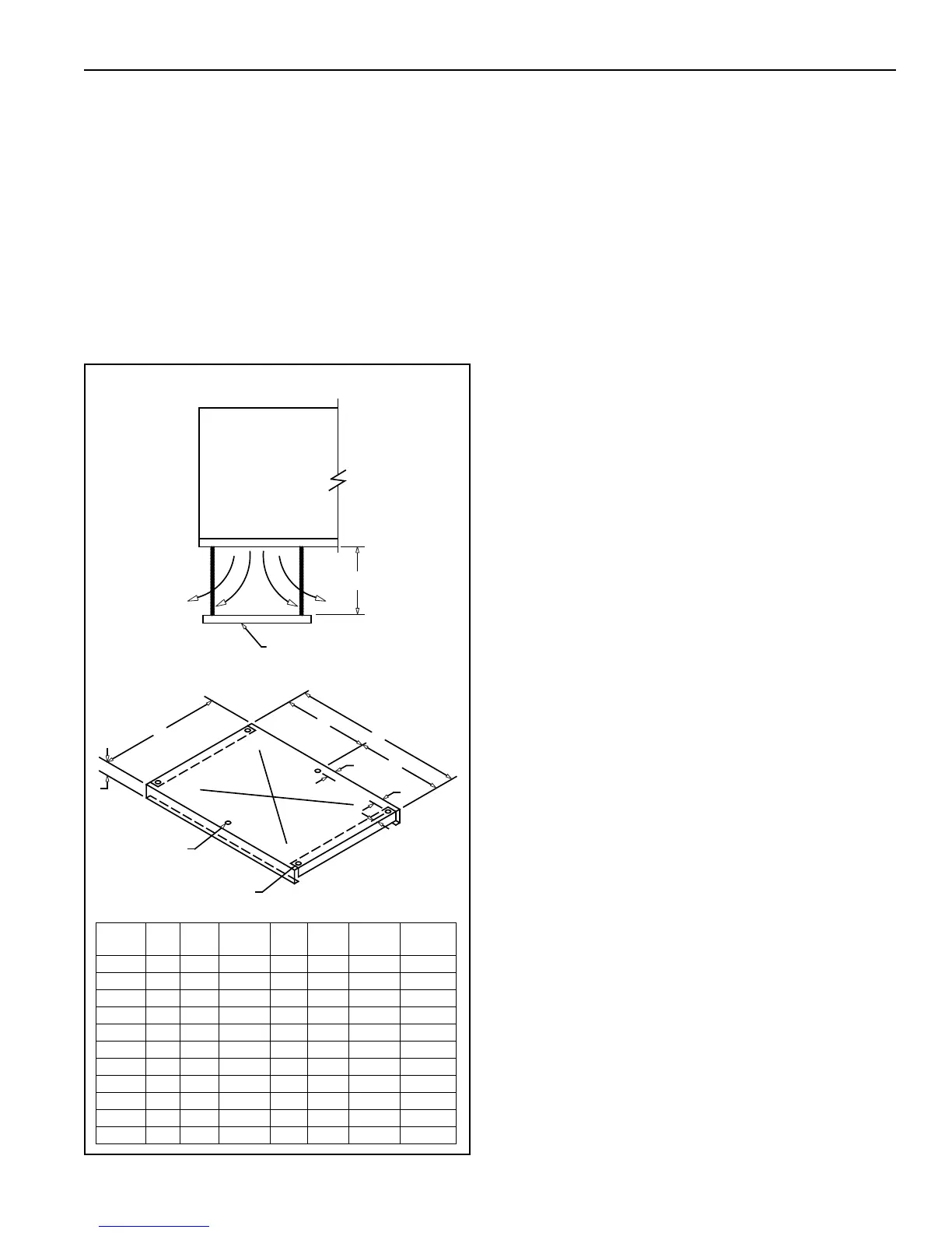
14.2 Splash Plate Installation
The splash plate is designed to hang, supported by
suspension rods (rods provided by others) directly
below the bottom discharge opening of a horizontal
air handler. The center point of the splash plate must
be located at the center point of the discharge
opening and be positioned below the air handler
within the range of dimensions show below as E
(min) & E (max.). For model sizes 60-89, center
support rods will be required (see illustration below).
NOTE: Be sure to include provisions in the stru cture
suspending the discharge plate that will prevent
sway/movement of the plate when the supply fan is in
operation.
To attach all of the hanger rods to the splash plate,
start by threading a flanged nut onto each hanger
rod. Then, slip each hanger rod down through a hole
located in each corner of the splash plate. Next, feed
a flanged nut onto the rod below the splash plate.
Adju sting the nuts will level the splash plate. Torque
hardware after leveling.
FIGURE 50: Discharge Plate
DISCHARGE PLATE
SUPPORT RODS
(BY OTHERS)
FAN SECTION
CENTER HOLES
ON 60 THRU 89
13
/16” HOLES
1¾” TYPICAL
4 CORNERS
2”
2”
TYPICAL
D
B
D
A
C
E
RIGHT SIDE VIEW
Model A B C D
E
(min.)
E
(max.)
Weight
(lbs)
4024 42 54 3 - 25 38 80
4036 47 72 3 - 36 54 110
4040 55 75 3 - 42 64 130
4044 58 81 3 - 46 70 140
4049 61 88 3 - 50 75 160
4054 65 97 3 - 56 84 180
4060 70 106 3 53 64 96 230
4066 72 116 3 58 70 105 250
4073 72 124 3 62 75 112 260
4080 82 140 4 70 88 132 330
4089 82 140 4 70 88 132 330