SECTION 19: ELECTRICAL
77 of 154
located on the blower motor. Current draw may be
adjusted downward by reducing blower rotations per
minute (RPM) or by increasing external static
pressure.
19.5 Control Current Draw
The maximum current draw for an air handler’s
controls and accessories is 3A.
19.6 Safety Systems
Safety systems are required for proper performance
of the air handler. The air handler shall not be
permitted to operate with any safety system disabled.
If a fault is found in any of the safety systems, then
the system shall be repaired only by a contractor
qualified in the installation and service of gas fired
heating equipment, using only components that are
sold and supplied by Rapid Engineering LLC. Refer
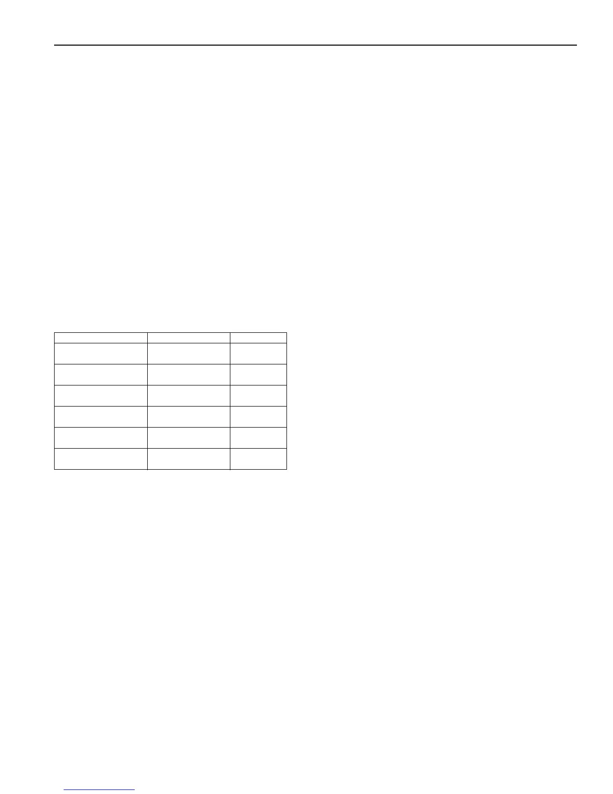
to Page 81, Table 31 for a brief description of each
safety device, its location and its switching voltage.
Table 30: Safety Systems
19.6.1 Manual Reset High Temperature Limit
Switch
If for any reason, the temperature of the air at the
discharge of the blower reaches the limit set point of
160° F (71.1° C), the high temperature limit switch will
open the circuit to the burner system and discontinue
all burner functions. E
vents that could result in
excessive discharge air temperatures include if the
burner modulation amplifier is defective (i.e.
temperature sensor goes open circuit) or if a surge in
gas pressure reaches the burner. Restarting of the
burner can only be accomplished after the limit has
cooled down and the reset button on the switch has
been depressed. This switch is located on the blower
housing inside the air handler.
19.6.2 Pressure Switches
The low airflow velocity pressure switch monitors the
airflow (differential pressure) across the burner.
When the airflow across the burner reaches the
proper velocity (volume) for combustion, the switch
closes. When the switch closes, it permits the flame
safeguard relay to begin ignition. This switch is
factory set at 0.32 in wc (0.8 mbar). The high velocity
pressure s
witch will open if the airflow across the
burner reaches its maximum allowable limit. This
switch is factory set at 1.40 in wc (3.5 mbar). The
pressure switch is a safety device, which cannot be
field-adjusted or tampered with.
19.6.3 Gas Pressure Switches
Gas pressure switches are standard on certain
models (FM compliant gas trains above 2,500 MBH
and XL compliant gas trains) and are also available
as an option on the others.
The function of the gas pressure switches is to
protect against insufficient, lack of gas pressure and
excessive pressure in the system.
On the low gas pressure switch side, this switch
opens its internal switch which shuts the burner down
and prevents its operation due to insufficient gas
pressure.
On the high gas pressure switch side, its internal
switch w
ill open, shutting down the burner due to
excessive gas pressure passing through the gas
train.
The settings of the gas pressure switches are field
adjustable. The one monitoring the incoming gas
pressure is the low gas pressure switch. The low gas
pressure switch must be set to the minimum required
gas pressure as indicated on the data plate.
The high gas pressure switch must be set to 1 in w.c.
(2.5 mbar) above high fire setting established during
commissioning.
The switch will have to be reset manually, once the
condition has been corrected.
Safety Controls Location Voltage
Manual Reset High-
Temp Limit (All Models)
Blower Discharge 120
Pressure Switches
(All Models)
Air Handler Control
Enclosure
120
Flame Control
(2010/2010B/2020/2030)
Air Handler Control
Enclosure
120
Flame Control (2005)
Air Handler Control
Enclosure
24
Discharge Temperature
Monitor (All Models)
Blower Discharge 24
AM Resistor
(AM/VAV Style)
Air Handler Control
Enclosure
24