4000-SERIES INSTALLATION, OPERATION AND SERVICE MANUAL
16 of 154
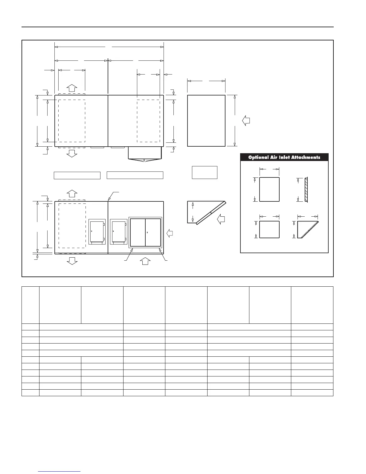
FIGURE 9: 4000 FR Horizontal Model Dimensions
Table 7: 4000 FR Approximate Shipping Weights
B
Q
Z
UD
F
BD
LD/RD
80%
(Optional)
GAS CONNECTION
80%
(Optional)
W
OA
A
OA
X
T
S
R
BR
P
R
CE
FJ
E
C
D
L
J
K
M
A
K
RD
BD/UD
CE
FJ
ELECTRICAL
CONNECTION
LD
AD1AD2
AD1AD2
PLAN VIEW
RIGHT SIDE
VIEW
ER
BR
FAN SECTION
BURNER SECTION
INLET HOOD
(OPTIONAL)
N
A x U
A x U
N
A x W
A x W
X
FILTERS
Outdoor Air
Duct Sleeve
Filtered Inlet
Hood
Louver Duct Louver
Model
Horizontal
Fan Section
Horizontal
Burner Section
Filter Section
Inlet Hood
Vertical
Fan Section
Vertical
Burner Section
Filter Stand
4024
1,245 320 80 1,230 95
4036
2,055 465 135 2,054 140
4040
2,354 525 210 2,360 150
4044
2,716 600 226 2,704 160
4049
3,034 640 248 3,017 175
4054
2,383 1,470 685 370 2,373 1,553 320
4060
2,673 1,712 760 395 2,663 1,805 350
4066
2,961 1,847 875 410 3,129 1,949 400
4073
4,219 1,994 1,125 425 4,553 2,203 450
4080
3,667 4,359 1,400 590 4,002 4,493 500
4089
4,101 4,418 1,400 590 4,503 4,552 500