9. Interrupts
puorG92/C61M
page 82
854fo7002,03.raM21.1.veR
2110-1010B90JER
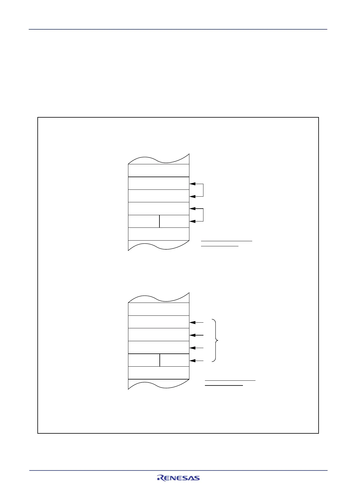
Figure 9.8 Operation of Saving Register
The operation of saving registers carried out in the interrupt sequence is dependent on whether the SP
(1)
,
at the time of acceptance of an interrupt request, is even or odd. If the stack pointer
(1)
is even, the FLG
register and the PC are saved, 16 bits at a time. If odd, they are saved in two steps, 8 bits at a time.
Figure 9.8 shows the operation of the saving registers.
NOTE:
1. When any INT instruction in software numbers 32 to 63 has been executed, this is the SP indicated
by the U flag. Otherwise, it is the ISP.
(2) SP contains odd number
[SP] (Odd)
[SP] – 1 (Even)
[SP] – 2 (Odd)
[SP] – 3 (Even)
[SP] – 4 (Odd)
[SP] – 5 (Even)
Address
Sequence in which order
registers are saved
(2)
(1)
Finished saving registers
in four operations.
(3)
(4)
(1) SP contains even number
[SP] (Even)
[SP] – 1 (Odd)
[SP] – 2 (Even)
[SP] – 3 (Odd)
[SP] – 4 (Even)
[SP] – 5 (Odd)
NOTE:
1. [SP] denotes the initial value of the SP when interrupt request is acknowledged.
After registers are saved, the SP content is [SP] minus 4.
Address
PC
M
Stack
FLG
L
PCL
Sequence in which order
registers are saved
(2) Saved simultaneously,
all 16 bits
(1) Saved simultaneously,
all 16 bits
Finished saving registers
in two operations.
PC
M
Stack
FLG
L
PCL
Saved, 8 bits at a time
FLG
H PCH
FLGH
PCH
 Loading...


