puorG92/C61M
22. Usage Notes
page 427
854fo7002,03.raM21.1.veR
2110-1010B90JER
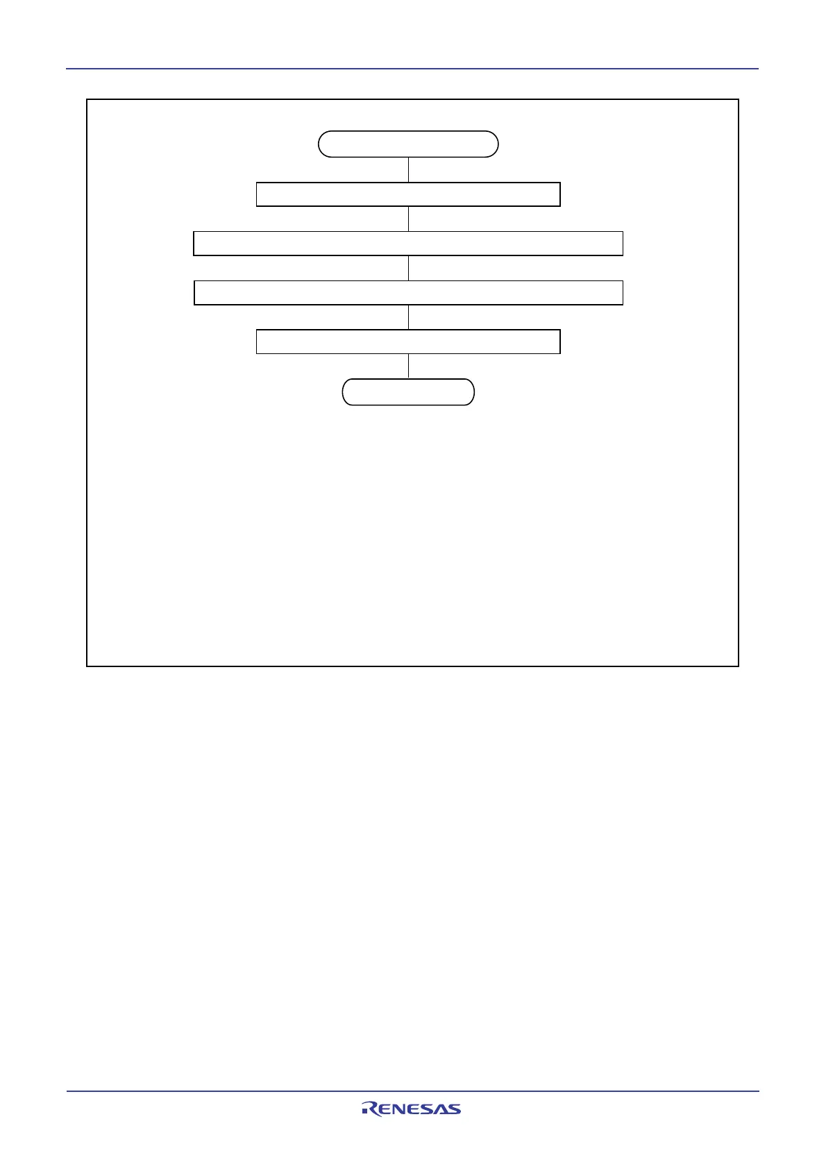
NOTES:
1.The above settings must be executed individually. Do not execute two or more settings
simultaneously (using one instruction).
2. Use the I flag for the INTi interrupt (i = 0 to 5).
For the interrupts from peripheral functions other than the INTi interrupt, turn off the
peripheral function that is the source of the interrupt in order not to generate an interrupt
request before changing the interrupt generate factor. In this case, if the maskable interrupts
can all be disabled without causing a problem, use the I flag. Otherwise, use the corresponding
bits ILVL2 to ILVL0 for the interrupt whose interrupt generate factor is to be changed.
3. Refer to 22.4.6 Rewrite the Interrupt Control Register for details about the
instructions to use and the notes to be taken for instruction execution.
Changing the interrupt source
Disable interrupts
(2,3)
Use the MOV instruction to clear the IR bit to 0 (interrupt not requested)
(3)
Change the interrupt generate factor (including a mode change of peripheral function)
Enable interrupts
(2,3)
End of change
IR bit: A bit in the interrupt control register for the interrupt whose interrupt generate factor is to
be changed
Figure 22.2 Procedure for Changing the Interrupt Generate Factor
______
22.4.5 INT Interrupt
1. Either an “L” level of at least tW(INH) or an “H” level of at least tW(INL) width is necessary for the signal
input to pins INT0 through INT5 regardless of the CPU operation clock.
2. If the POL bit in registers INT0IC to INT5IC or bits IFSR7 to IFSR0 in the IFSR register are changed,
the IR bit may inadvertently set to 1 (interrupt requested). Be sure to clear the IR bit to 0 (interrupt not
requested) after changing any of those register bits.
3. When using the INT5 interrupt for exiting stop mode, set the P17DDR register to FF16 (disable digital
debounce filter) before entering stop mode.
 Loading...


