puorG92/C61M
22. Usage Notes
page 444
854fo7002,03.raM21.1.veR
2110-1010B90JER
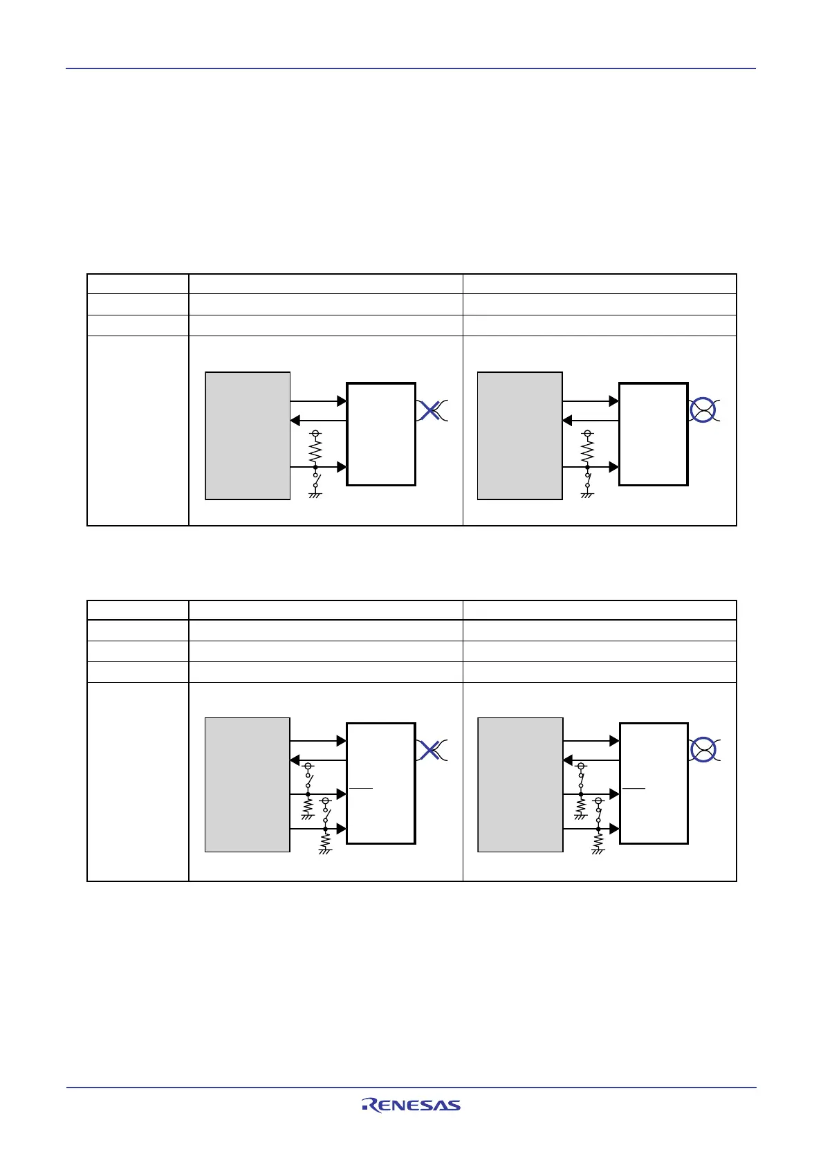
22.11.2 CAN Transceiver in Boot Mode
When programming the flash memory in boot mode via CAN bus, the operation mode of CAN transceiver
should be set to “high-speed mode” or “normal operation mode”. If the operation mode is controlled by the
MCU, CAN transceiver must be set the operation mode to “high-speed mode” or “normal operation mode”
before programming the flash memory by changing the switch etc. Tables 22.3 and 22.4 show pin con-
nections of CAN transceiver.
Table 22.3 Pin Connections of CAN Transceiver (In case of PCA82C250: Philips product)
Standby mode High-speed mode
Rs pin
(Note 1)
“H”“L”
CAN communication
impossible possible
Connection
M16C/29
PCA82C250
CTx
0
CRx0
Port
(2)
TxD
RxD
Rs
CANH
CANL
Switch OFF
M16C/29
PCA82C250
CTx
0
CRx0
TxD
RxD
Rs
CANH
CANL
Port
(2)
Switch ON
Sleep mode Normal operation mode
_______
STB pin (Note 1)
“L”“H”
EN pin
(Note 1)
“L”“H”
CAN communication
impossible possible
Connection
M16C/29
PCA82C252
CTx
0
CRx0
TxD
RxD
STB
CANH
CANL
EN
Switch OFF
Por
t
(2)
Por
t
(2)
M16C/29
PCA82C252
CTx
0
CRx
0
TxD
RxD
STB
CANH
CANL
EN
Port
(2)
Port
(2)
Switch ON
Note 1: The pin which controls the operation mode of CAN transceiver.
Note 2: Connect to enabled port to control CAN transceiver.
Table 22.4 Pin Connections of CAN Transceiver (In case of PCA82C252: Philips product)
Note 1: The pin which controls the operation mode of CAN transceiver.
Note 2: Connect to enabled port to control CAN transceiver.
 Loading...


