9. Interrupts
puorG92/C61M
page 85
854fo7002,03.raM21.1.veR
2110-1010B90JER
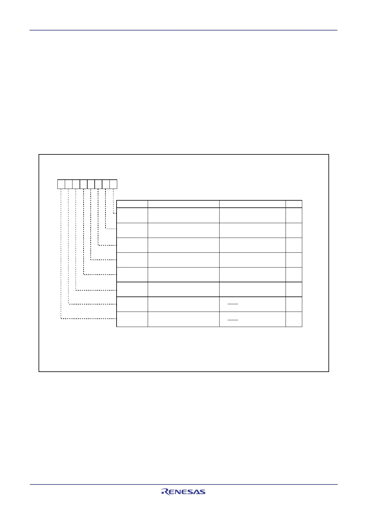
Interrupt Request Cause Select Register
Bit Name Function
Bit Symbol
RW
Symbol Address After Reset
IFSR 035F
16
00
16
IFSR0
b7 b6 b5 b4 b3 b2 b1 b0
INT0 interrupt polarity
switching bit
0 : SI/O3
1 : INT4
0 : SI/O4
1 : INT5
0 : One edge
1 : Both edges
0 : One edge
1 : Both edges
0 : One edge
1 : Both edges
0 : One edge
1 : Both edges
0 : One edge
1 : Both edges
INT1 interrupt polarity
switching bit
INT2 interrupt polarity
switching bit
INT3 interrupt polarity
switching bit
INT4 interrupt polarity
switching bit
INT5 interrupt polarity
switching bit
0 : One edge
1 : Both edges
Interrupt request cause
select bit
Interrupt request cause
select bit
IFSR1
IFSR2
IFSR3
IFSR4
IFSR5
IFSR6
IFSR7
RW
RW
RW
RW
RW
RW
RW
RW
(1)
(1)
(1)
(1)
(1)
(1)
(2)
NOTES:
1. When setting this bit to 1 (both edges), make sure the POL bit in registers INT0IC to INT5IC is set to
0 (falling edge).
2. When setting this bit to 0 (SI/O3, SI/O4), make sure the POL bit in registers S3IC and S4IC is set to
0 (falling edge).
(2)
______
9.6 INT Interrupt
_______
INTi interrupt (i=0 to 5) is triggered by the edges of external inputs. The edge polarity is selected using the
IFSRi bit in the IFSR register.
________
The INT5 input has an effective digital debounce function for a noise rejection. Refer to "19.6 Digital
________
Debounce function" for this detail. When using INT5 interrupt to exit stop mode, set the P17DDR register
to FF16 before entering stop mode.
________ ________ ________
To use the INT4 interrupt, set the IFSR6 bit in the IFSR register to 1 (INT4). To use the INT5 interrupt, set
________
the IFSR7 bit in the IFSR register to 1 (INT5).
After modifiying bit IFSR6 or IFSR7, clear the corresponding IR bit to 0 (interrupt not requested) before
enabling the interrupt.
Figure 9.11 shows the IFSR registers.
Figure 9.11 IFSR Register
 Loading...


