16. MULTI-MASTER I
2
C bus INTERFACE
puorG92/C61M
page 278
854fo7002,03.raM21.1.veR
2110-1010B90JER
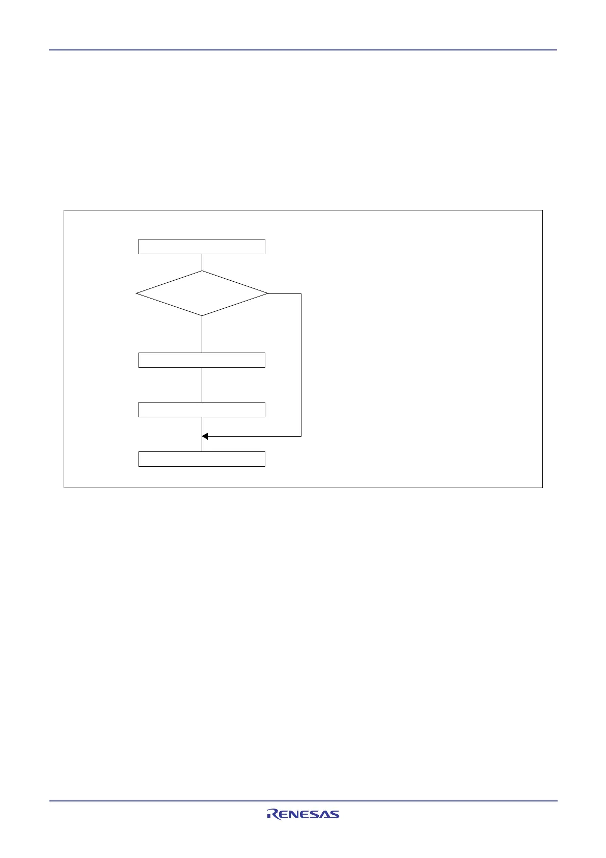
16.9 START Condition Generation Method
Set the MST bit, TRX bit and BB flags in the S10 register to 1 and set the PIN bit and 4 low-order bits in the
S10 register to 0 simultaneously, to enter START condition standby mode, when the ES0 bit in the S1D0
register is set to 1 (I
2
C bus interface enabled) and the BB flag is set to 0 (bus free). When the slave address
is written to the S00 register next, START condition is generated and the bit counter is reset to 0002 and 1-
byte SCL signal is output. The START condition generation timing varies between standard clock mode
and high-speed clock mode. See Figure 16.16 and Table 16.8.
Figure 16.14 Start condition generation flow chart
I
n
t
e
r
r
u
p
t
d
i
s
a
b
l
e
BB=0?
S10 = E016
S00 = Data
Interrupt enable
N
o
Yes
Start condition trigger generation
Start condition standby status setting
*Data = Slave address data
 Loading...


