7. Clock Generation Circuit
page 60
854fo7002,03.raM21.1.veR
2110-1010B90JER
puorG92/C61M
7.6.1.6 On-chip Oscillator Mode
The selected on-chip oscillator clock divided by 1 (undivided), 2, 4, 8 or 16 provides the CPU clock.
The on-chip oscillator clock is also the clock source for the peripheral function clocks. If the sub clock
is on, fC32 can be used as the count source for timers A and B. The on-chip oscillator frequency can be
selected by bits ROCR3 to ROCR0 in the ROCR register. When the operation mode is returned to the
high and medium speed modes, set the CM06 bit to 1 (divided by 8 mode).
7.6.1.7 On-chip Oscillator Low Power Dissipation Mode
The main clock is turned off after being placed in on-chip oscillator mode. The CPU clock can be se-
lected as in the on-chip oscillator mode. The on-chip oscillator clock is the clock source for the periph-
eral function clocks. If the sub clock is on, f
C32
can be used as the count source for timers A and B.
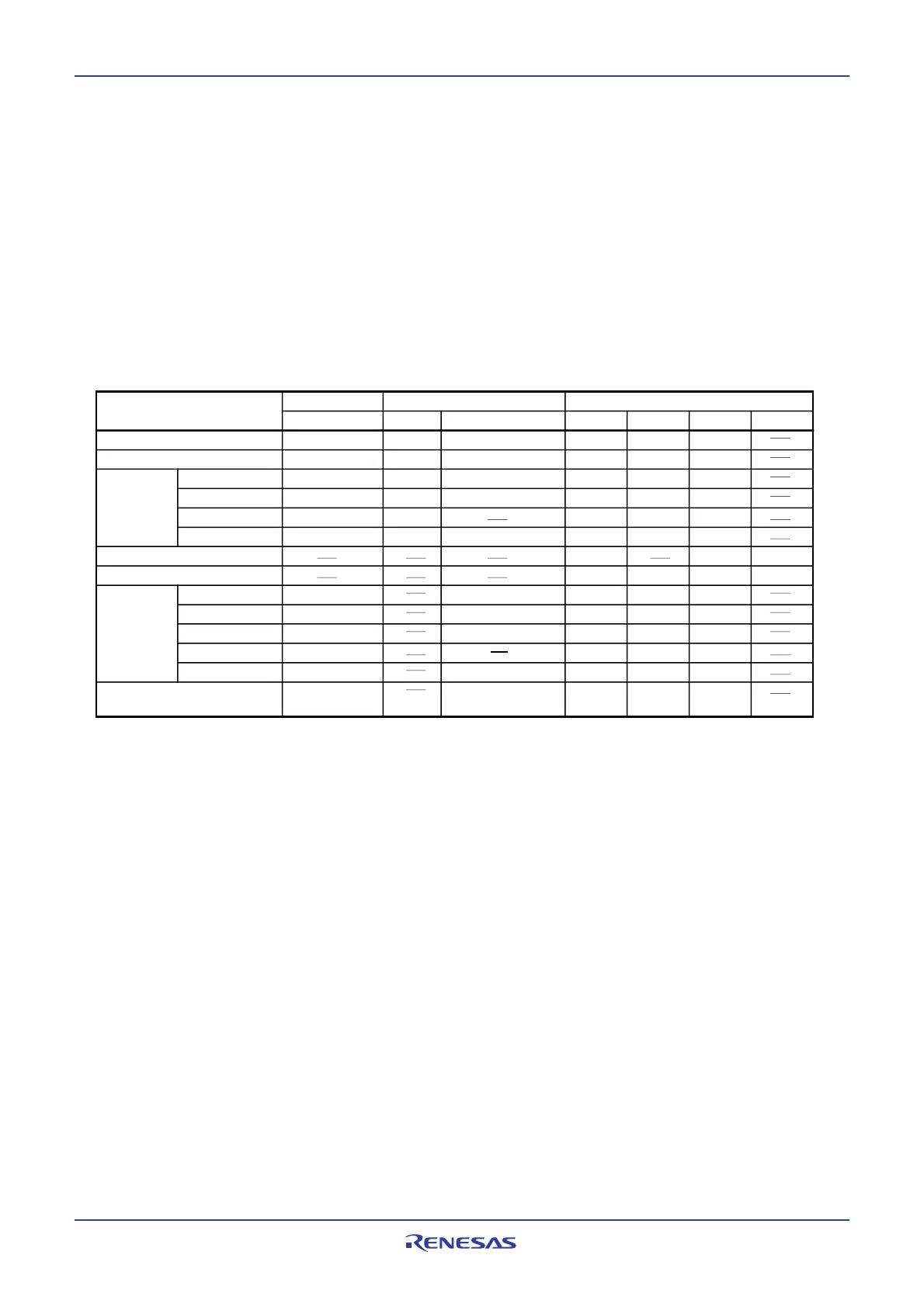
Table 7.4 Setting Clock Related Bit and Modes
7.6.2 Wait Mode
In wait mode, the CPU clock is turned off, so are the CPU (because operated by the CPU clock) and the
watchdog timer. However, if the PM22 bit in the PM2 register is 1 (on-chip oscillator clock for the watch-
dog timer count source), the watchdog timer remains active. Because the main clock, sub clock, on-chip
oscillator clock and PLL clock all are on, the peripheral functions using these clocks keep operating.
7.6.2.1 Peripheral Function Clock Stop Function
When the CM02 bit is 1 (peripheral function clocks turned off during wait mode), f1, f2, f8, f32, f1SIO,
f2SIO, f8SIO, f32SIO, and fAD stop running in wait mode to reduce power consumption. However, fC32
remains active.
7.6.2.2 Entering Wait Mode
The MCU enters wait mode by executing the WAIT instruction.
When the CM11 bit is set to 1 (CPU clock source is the PLL clock), be sure to clear the CM11 bit to 0
(CPU clock source is the main clock) before going to wait mode. The power consumption of the chip
can be reduced by clearing the PLC07 bit to 0 (PLL stops).
1
(1)
Modes
CM2 Register
CM21
CM1 Register
CM11 CM17, CM16
CM0 Register
CM07 CM06 CM05
CM04
PLL operation mode 01002 00
High-speed mode 0 0 00
2 000
Medium-
speed
mode
0001
2 000
0010
2 000
divided by 2
00 01
0
0011
2 000
Low-speed mode 1 0
1
Low power dissipation mode
11
On-chip
oscillator
mode
(3)
1
divided by 4
divided by 8
divided by 16
On-chip oscillator low power
dissipation mode
NOTES:
1. When the CM05 bit is set to 1 (main clock turned off) in low-speed mode, the mode goes to low power
dissipation mode and CM06 bit is set to 1(divided by 8 mode) simultaneously.
2. The divide-by-n value can be selected the same way as in on-chip oscillator mode.
3. On-chip oscillator frequency can be any of those described in the section 7.6.1.6 On-chip Oscillator Mode.
0
0
101
2 000
110
2 000
110
111
2 000
100
2 000
(2)
divided by 2
divided by 4
divided by 8
divided by 16
divided by 1
1
(1)
(2)
1
0
 Loading...


