7. Clock Generation Circuit
page 68
854fo7002,03.raM21.1.veR
2110-1010B90JER
puorG92/C61M
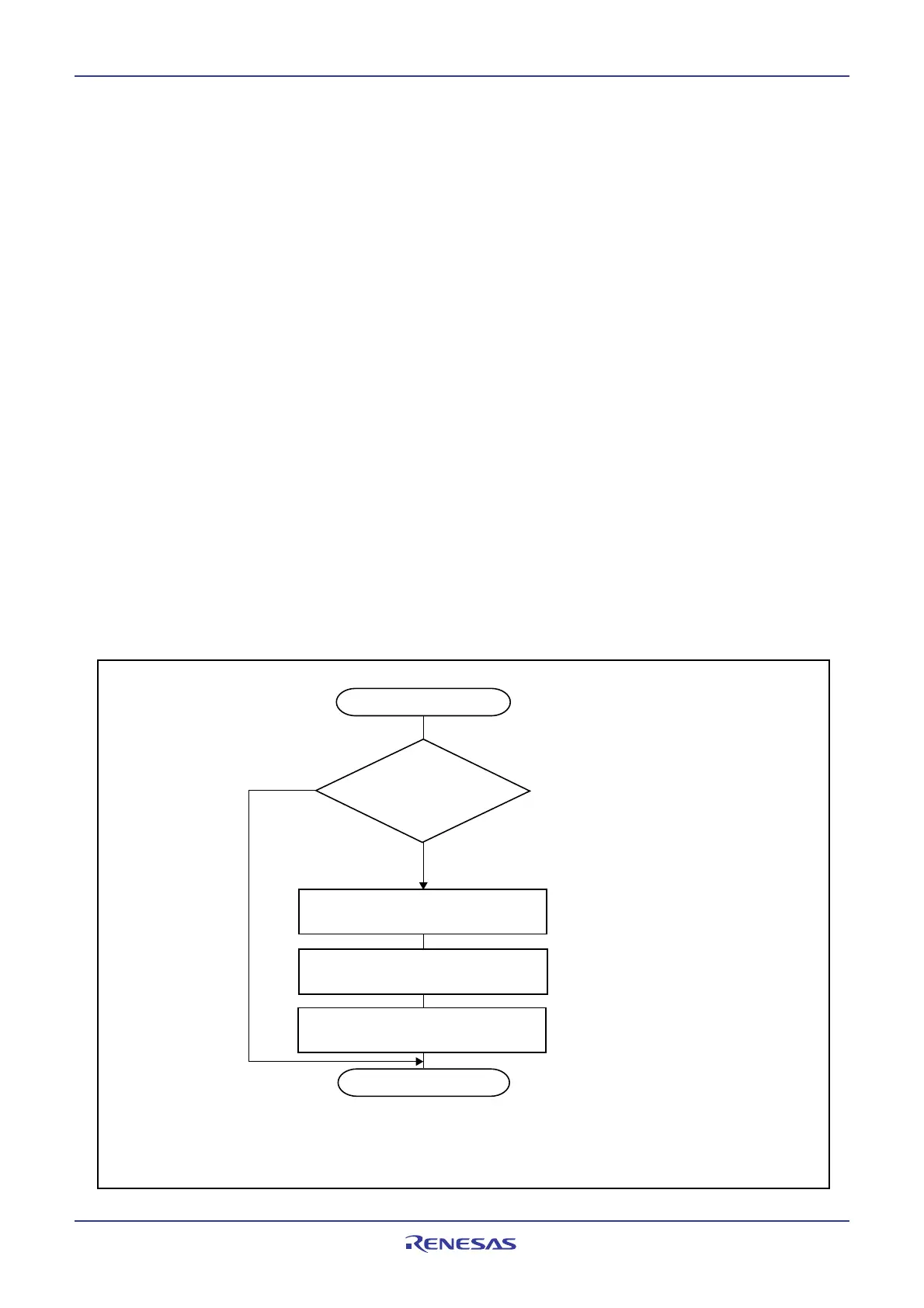
Switch to the main clock
Determine several times whether
the CM23 bit is set to 0
(main clock oscillates)
Set the CM22 bit to 0
("oscillatin stop, re-oscillation" not detected)
Set the CM06 bit to 1
(divide-by-8 mode)
Set the CM21 bit to 0
(main clock or PLL clock)
CM06: Bit in the CM0 register
CM23 to CM21: Bits in the CM2 register
Yes
No
End
NOTE:
1. If the clock source for CPU clock is to be changed to PLL clock, set to PLL operation
mode after set to high-speed mode.
7.8.3 How to Use Oscillation Stop and Re-oscillation Detect Function
• The oscillation stop and re-oscillation detect interrupt shares the vector with the watchdog timer inter-
rupt. If the oscillation stop, re-oscillation detection and watchdog timer interrupts both are used, read
the CM22 bit in an interrupt routine to determine which interrupt source is requesting the interrupt.
• Where the main clock re-oscillated after oscillation stop, return the main clock to the CPU clock and
peripheral function clock source by program. Figure 7.13 shows the procedure for switching the clock
source from the on-chip oscillator to the main clock.
• Simultaneously with oscillation stop, re-oscillation detection interrupt occurrence, the CM22 bit be-
comes 1. When the CM22 bit is set at 1, oscillation stop, re-oscillation detection interrupt are disabled.
By setting the CM22 bit to 0 by program, oscillation stop, re-oscillation detection interrupt are enabled.
• If the main clock stops during low speed mode where the CM20 bit is 1, an oscillation stop, re-oscillation
detection interrupt request is generated. At the same time, the on-chip oscillator starts oscillating. In
this case, although the CPU clock is derived from the sub clock as it was before the interrupt occurred,
the peripheral function clocks now are derived from the on-chip oscillator clock.
• To enter wait mode while using the oscillation stop, re-oscillation detection function, set the CM02 bit to
0 (peripheral function clocks not turned off during wait mode).
• Since the oscillation stop, re-oscillation detection function is provided in preparation for main clock stop
due to external factors, set the CM20 bit to 0 (Oscillation stop, re-oscillation detection function disabled)
where the main clock is stopped or oscillated by program, that is where the stop mode is selected or the
CM05 bit is altered.
• This function cannot be used if the main clock frequency is 2 MHz or less. In that case, set the CM20 bit
to 0.
Figure 7.13 Procedure to Switch Clock Source From On-chip Oscillator to Main Clock
 Loading...


