12. Timers
puorG92/C61M
page 101
854fo7002,03.raM21.1.veR
2110-1010B90JER
12. Timers
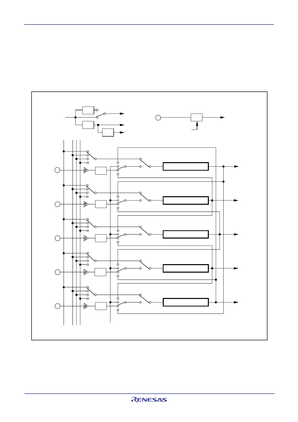
Eight 16-bit timers, each capable of operating independently of the others, can be classified by function as
either timer A (five) and timer B (three). The count source for each timer acts as a clock, to control such
timer operations as counting, reloading, etc. Figures 12.1 and 12.2 show block diagrams of timer A and
timer B configuration, respectively.
Figure 12.1 Timer A Configuration
• Timer mode
• One-shot timer mode
• Pulse Width Measuring (PWM) mode
• Timer mode
• One-shot timer mode
• PWM mode
• Timer mode
• One-shot timer mode
• PWM mode
• Timer mode
• One-shot timer mode
• PWM mode
• Timer mode
• One-shot timer mode
• PWM mode
• Event counter mode
• Event counter mode
• Event counter mode
• Event counter mode
• Event counter mode
TA0
IN
TA1
IN
TA2
IN
TA3
IN
TA4
IN
Timer A0
Timer A1
Timer A2
Timer A3
Timer A4
f
8
f
32
f
C32
Timer A0 interrupt
Timer A1 interrupt
Timer A2 interrupt
Timer A3 interrupt
Timer A4 interrupt
Noise
filter
Noise
filter
Noise
filter
Noise
filter
Noise
filter
1/32
f
C32
1/8
1/4
f
1 or
f
2
f
8
f
32
• Main clock
• PLL clock
• On-chip oscillator
clock
X
CIN
Set the CPSR bit in the
CPSRF register to 1
(prescaler reset)
Reset
Clock prescaler
Timer B2 overflow or underflow
1/2
f
1
f
2
PCLK0 bit = 0
PCLK0 bit = 1
f
1 or
f
2
 Loading...


