12. Timer
page 102
puorG92/C61M
854fo7002,03.raM21.1.veR
2110-1010B90JER
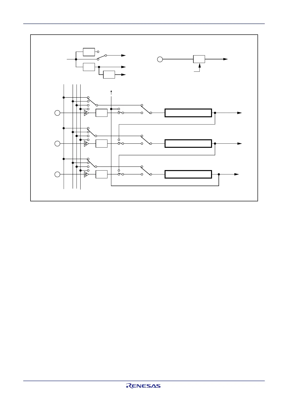
Figure 12.2. Timer B Configuration
• Event counter mode
• Event counter mode
• Event counter mode
• Timer mode
• Pulse width measuring mode,
pulse period measuring mode
• Timer mode
• Pulse width measuring mode,
pulse period measuring mode
• Timer mode
• Pulse width measuring mode,
pulse period measuring mode
TB0IN
TB1IN
TB2IN
Timer B0
Timer B1
Timer B2
f
8 f32 fC32
Timer B0 interrupt
Noise
filter
Noise
filter
Noise
filter
1/32
f
C32
XCIN
Reset
Clock prescaler
Timer B2 overflow or underflow ( to Timer A count source)
Timer B1 interrupt
Timer B2 interrupt
1/8
1/4
f
8
f32
1/2
f1 or f2
• Main clock
• PLL clock
• On-chip oscillator
clock
Set the CPSR bit in the
CPSRF register to 1
(prescaler reset)
f
1
f2
PCLK0 bit = 0
PCLK0 bit = 1
f
1 or f2
 Loading...


