16. MULTI-MASTER I
2
C bus INTERFACE
puorG92/C61M
page 279
854fo7002,03.raM21.1.veR
2110-1010B90JER
16.11 STOP Condition Generation Method
When the ES0 bit in the S1D0 register is set to 1 (I
2
C bus interface enabled) and bits MST and TRX in the
S10 register are set to 1 at the same time, set the BB flag, PIN bit and 4 low-order bits in the S10 register to
0 simultaneously, to enter STOP condition standby mode. When dummy data is written to the S00 register
next, the STOP condition is generated. The STOP condition generation timing varies between standard
clock mode and high-speed clock mode. See Figure 16.17 and Table 16.8.
Until the BB flag in the S10 register becomes 0 (bus free) after an instruction to generate the STOP condi-
tion is executed, do not write data to registers S10 and S00. Otherwise, the STOP condition waveform may
not be generated correctly.
If an input signal level of the SCL pin is set to low ("L") after the instruction to generate the STOP condition
is executed, a signal level of the SCL pin becomes high ("H"), and the BB flag is set to 0 (bus free), the MCU
outputs an "L" signal to SCL pin.
In that case, the MCU can stop an "L" signal output to the SCL pin by generating the STOP condition, writing
0 to the ES0 bit in the S1D0 register (disabled), or writing 1 to the IHR bit in the S1D0 register (reset
release).
16.10 START Condition Duplicate Protect Function
A START condition is generated when verifying that the BB flag in the S10 register does not use buses.
However, if the BB flag is set to 1 (bus busy) by the START condition which other master device generates
immediately after the BB flag is verified, the START condition is suspended by the START condition dupli-
cate protect function. When the START condition duplicate protect function starts, it operates as follows:
•Disable the start condition standby setting
If the function has already been set, first exit START condition standby mode and then set bits MST and
TRX in the S10 register to 0.
•Writing to the S00 register is disabled. (The START condition trigger generation is disabled)
•If the START condition generation is interrupted, the AL flag in the S10 register becomes 1.(arbitration
lost detection)
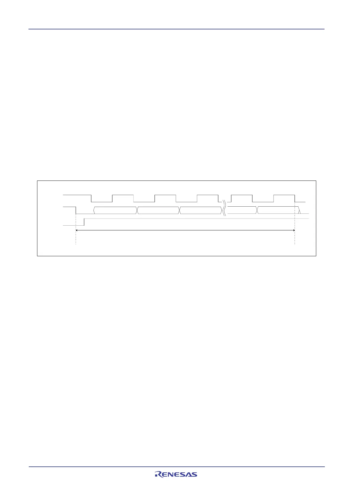
The START condition duplicate protect function is valid between the SDA falling edge of the START condi-
tion and the receive completion of the slave address. Figure16.15 shows the duration of the START
condition duplicate protect function.
Figure 16.15 The duration of the start condition duplicate protect function
1 clock
1 bit
S
CL
S
DA
BB flag
2 bit 3 bit
2 clock 3 clock
8 bit ACK bit
The duration of start condition duplicate protect
8 clock
ACK clock
 Loading...


