12. Timer (Three-phase Motor Control Timer Function)
puorG92/C61M
page 138
854fo7002,03.raM21.1.veR
2110-1010B90JER
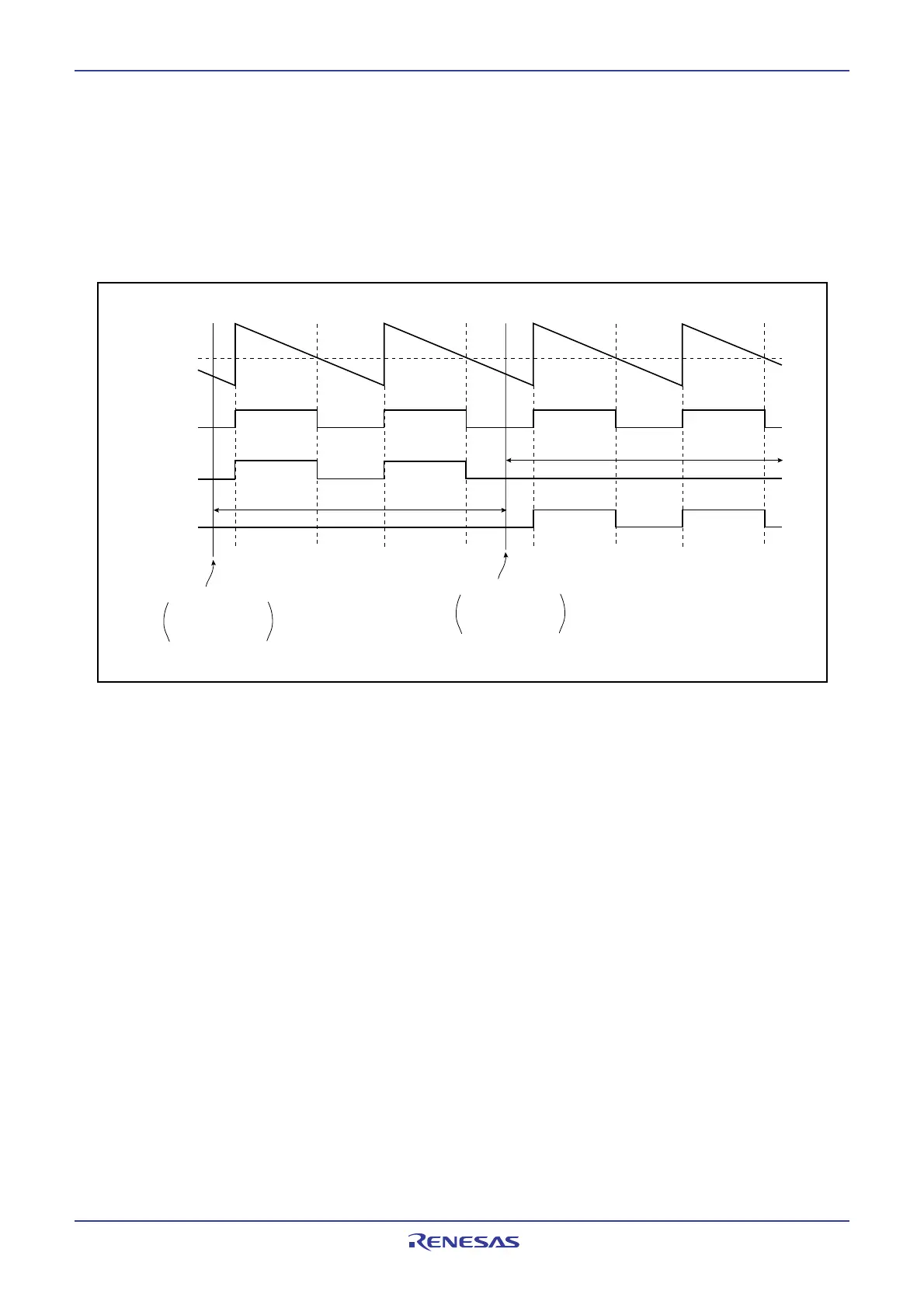
12.3.2 Three-phase/Port Output Switch Function
When the INVC03 bit in the INVC0 register set to 1 (Timer output enabled for three-phase motor control)
__
and setting the PFCi (i=0 to 5) in the PFCR register to 0 (I/O port), the three-phase PWM output pin (U, U,
__ ___
V, V, W and W) functions as I/O port. Each bit of the PFCi bits (i=0 to 5) is applicable for each one of
three-phase PWM output pins. Figure 12.37 shows the example of three-phase/port output switch func-
tion. Figure 12.38 shows the PFCR register and the three-phase protect control register.
Figure 12.37 Usage Example of Three-phse/Port Output Switch Function
Timer B2
U phase
V Phase
W phase
Writing PFCR register
PFC0 bit: 1
PFC2 bit: 1
PFC4 bit: 0
Functions as port P7
4
Functions as port P7
2
Writing PFCR register
PFC0 bit: 1
PFC2 bit: 0
PFC4 bit: 1
 Loading...


