9. Interrupts
puorG92/C61M
page 81
854fo7002,03.raM21.1.veR
2110-1010B90JER
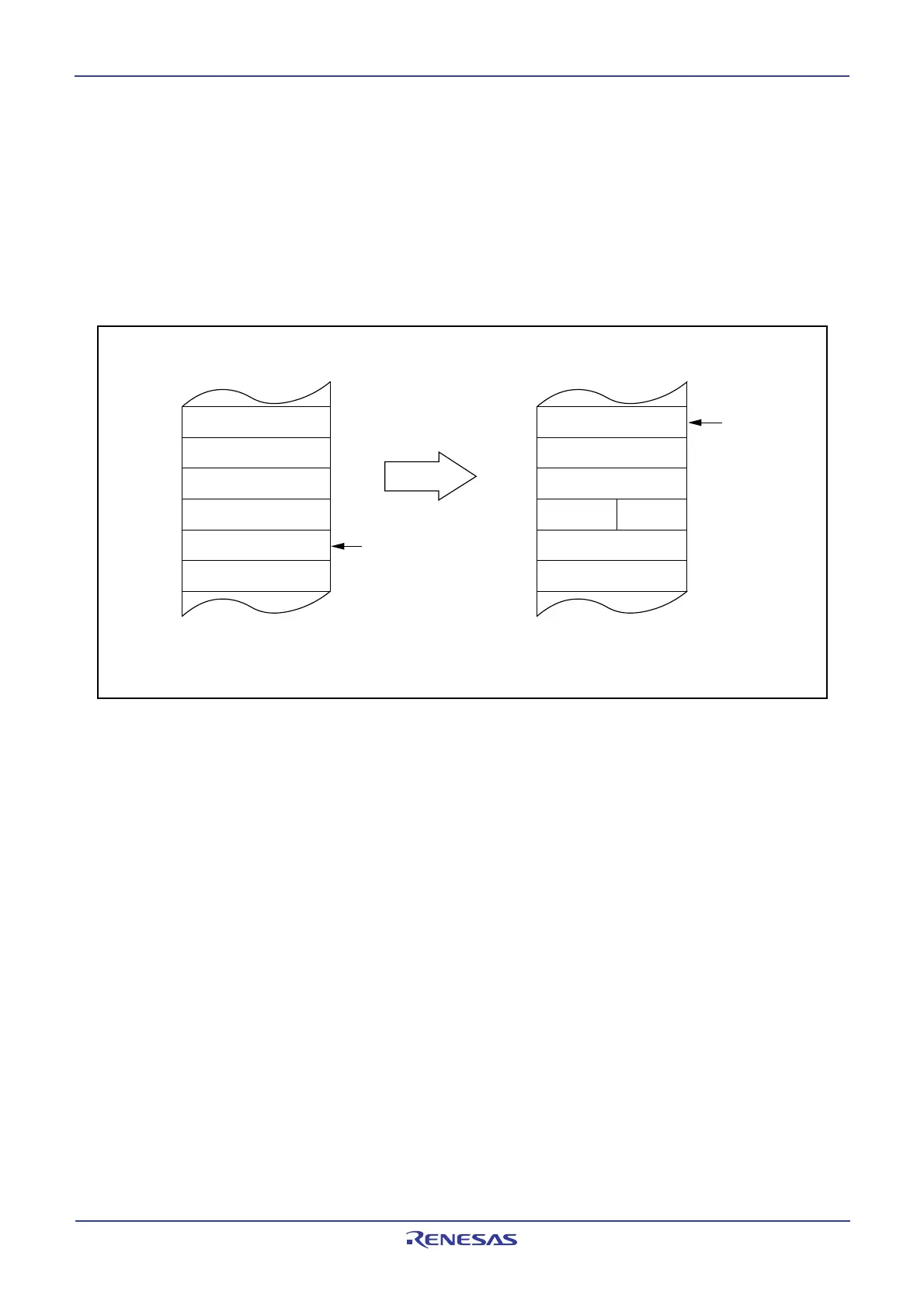
9.4.3 Saving Registers
In the interrupt sequence, the FLG register and PC are saved to the stack.
At this time, the 4 high-order bits of the PC and the 4 high-order (IPL) and 8 low-order bits of the FLG
register, 16 bits in total, are saved to the stack first. Next, the 16 low-order bits of the PC are saved.
Figure 9.7 shows the stack status before and after an interrupt request is accepted.
The other necessary registers must be saved in a program at the beginning of the interrupt routine. Use
the PUSHM instruction, and all registers except SP can be saved with a single instruction.
Figure 9.7 Stack Status Before and After Acceptance of Interrupt Request
Address
Content of previous stack
Stack
[SP]
SP value before
interrupt request is
accepted.
m
m – 1
m – 2
m – 3
m – 4
Stack status before interrupt request
is acknowledged
Stack status after interrupt request
is acknowledged
Content of previous stack
m + 1
MSB
LSB
m
m – 1
m – 2
m – 3
m – 4
Address
FLG
L
Content of previous stack
Stack
FLG
H
PC
H
[SP]
New SP value
Content of previous stack
m + 1
MSB LSB
PC
L
PC
M
 Loading...


