12. Timer B
puorG92/C61M
page 117
854fo7002,03.raM21.1.veR
2110-1010B90JER
12.2 Timer B
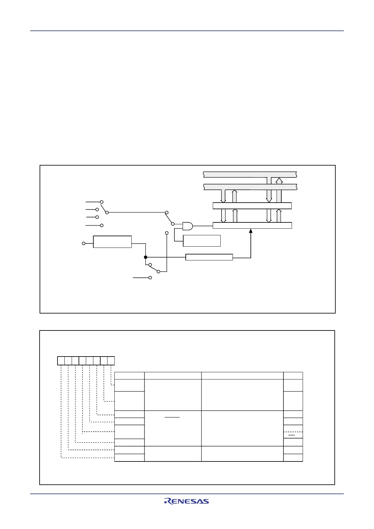
Figure 12.15 shows a block diagram of the timer B. Figures 12.16 and 12.17 show registers related to the
timer B.
Timer B supports the following four modes. Use bits TMOD1 and TMOD0 in the TBiMR register (i = 0 to 2)
to select the desired mode.
• Timer mode: The timer counts the internal count source.
• Event counter mode: The timer counts the external pulses or overflows and underflows of other timers.
• Pulse period/pulse width measurement mode: The timer measures the pulse period or pulse width of
external signal.
• A/D trigger mode: The timer starts counting by one trigger until the count value becomes 000016.
This mode is used together with simultaneous sample sweep mode or delayed trigger mode 0 of A/D
converter to start A/D conversion.
Figure 12.15 Timer B Block Diagram
Figure 12.16 TB0MR to TB2MR Registers
Clock source selection
• Event counter
Reload register
Low-order 8 bits
High-order 8 bits
Data bus low-order bits
Data bus high-order bits
f
8
TABSR register
Polarity switching,
edge pulse
Counter reset circuit
Counter
Clock selection
• Timer mode
• Pulse period/, pulse width measuring mode
• A/D trigger mode
f
1
or f
2
f
C32
f
32
TBj overflow
(1)
(j = i – 1, except j = 2 if i = 0)
Can be selected in
onlyevent counter mode
TBi
IN
(i = 0 to 2)
NOTE:
1. Overflow or underflow.
TBi Address TBj
Timer B0 0391
16
-
0390
16
Timer B2
Timer B1 0393
16
-
0392
16
Timer B0
Timer B2 0395
16
-
0394
16
Timer B1
Timer Bi Mode Register (i=0 to 2)
Symbol
After Reset
TB0MR to TB2MR
Bit Name
Function Bit Symbol
RW
b7 b6 b5 b4 b3 b2 b1 b0
b1 b0
TCK1
MR3
MR2
MR1
TMOD1
MR0
TMOD0
TCK0
Operation mode select bit
(1)
(2)
RW
RW
RW
RW
RW
RW
RW
RO
NOTES:
1. Timer B0.
2. Timer B1, Timer B2.
Function varies with each operation
mode
Count source select bit
Function varies with each operation
mode
Address
039B
16
to 039D
16
00XX0000
2
0 0 : Timer mode or A/D trigger mode
0 1 : Event counter mode
1 0 : Pulse period measurement mode,
pulse width measurement mode
1 1 : Do not set
 Loading...


