14. Serial I/O
puorG92/C61M
page 221
854fo7002,03.raM21.1.veR
2110-1010B90JER
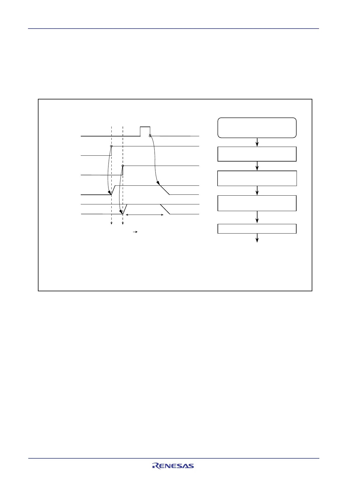
14.2.3 Functions for Setting an SOUTi Initial Value
If the SMi6 bit in SiC register is set to 0 (external clock), the SOUTi pin output level can be fixed high or low
when not transferring data. However, when transmitting data consecutively, the last bit (bit 0) value of the
last transmitted data is retained between the sccessive data transmissions. Figure 14.39 shows the
timing chart for setting an SOUTi initial value and how to set it.
Figure 14.39 SOUTi Initial Value Setting
S
i
g
n
a
l
w
r
i
t
t
e
n
t
o
S
i
T
R
R
r
e
g
i
s
t
e
r
S
O
U
T
i
(
i
n
t
e
r
n
a
l
)
S
M
i
7
b
i
t
S
OUT
i pin output
S
M
i
3
b
i
t
S
e
t
t
i
n
g
t
h
e
S
O
U
T
i
i
n
i
t
i
a
l
v
a
l
u
e
t
o
“
H
”
Port selection switching
(I/O port S
OUT
i)
D
0
(
i
=
3
,
4
)
I
n
i
t
i
a
l
v
a
l
u
e
=
“
H
”
(
3
)
Port output D 0
(
E
x
a
m
p
l
e
)
W
h
e
n
“
H
”
s
e
l
e
c
t
e
d
f
o
r
S
O
U
T
i
i
n
i
t
i
a
l
v
a
l
u
e
(
1
)
(
2
)
NOTES:
1. This diagram applies to the case where the bits in the SiC register are set as follows:
SMi2 = 0 (S
OUT
i output), SMi5 = 0 (LSB first) and SMi6 = 0 (external clock)
2. S
OUT
i can only be initialized when input on the CLKi pin is in the high state if the SMi4bit in the SiC
register is set to 0 (transmit data output at the falling edge of the transfer clock) or in the low state if
the SMi4 bit is set to 1 (transmit data output at the rising edge of the transfer clock).
3. If the SMi6 bit is set to 1 (internal clock) or if the SMi2 bit is set to 1 (S
OUTi
output disabled), this
output goes to the high-impedance state.
Setting of the initial value of S OUTi
output and starting of transmission/
reception
Set the SMi3 bit to 0
(S
OUTi pin functions as an I/O port)
Write to the SiTRR register
Serial transmit/reception starts
Set the SMi7 bit to 1
(S
OUTi initial value = “H”)
Set the SMi3 bit to 1
(S
OUTi pin functions as S OUTi output)
“H” level is output
from the S
OUTi pin
 Loading...


