7. Clock Generation Circuit
page 47
854fo7002,03.raM21.1.veR
2110-1010B90JER
puorG92/C61M
- CPU clock source
- Peripheral function
clock source
Use of clock
Main Clock
Oscillation Circuit
Sub Clock
Oscillation Circuit
Item
- CPU clock source
- Timer A, B's clock
source
Clock frequency 0 to 20 MHz 32.768 kHz
- Ceramic oscillator
- Crystal oscillator
Usable oscillator
- Crystal oscillator
X
IN, XOUT
Pins to connect
oscillator
X
CIN, XCOUT
Available
Oscillation stop,
restart function
Oscillating
Oscillator status
after reset
Stopped
Externally derived clock can be input
Other
PLL Frequency
Synthesize
r
10 to 20 MHz
Stopped
Variable On-chip Oscillator
- CPU clock source
- Peripheral function clock source
- CPU and peripheral function
clock sources when the main
clock stops oscillating
Selectable source frequency:
f
1(ROC), f2(ROC), f3(ROC)
Selectable divider:
by 2, by 4, by 8
Oscillating
- CPU clock source
- Peripheral function clock
sourc
e
(CPU clock source)
Available Available Available
7. Clock Generation Circuit
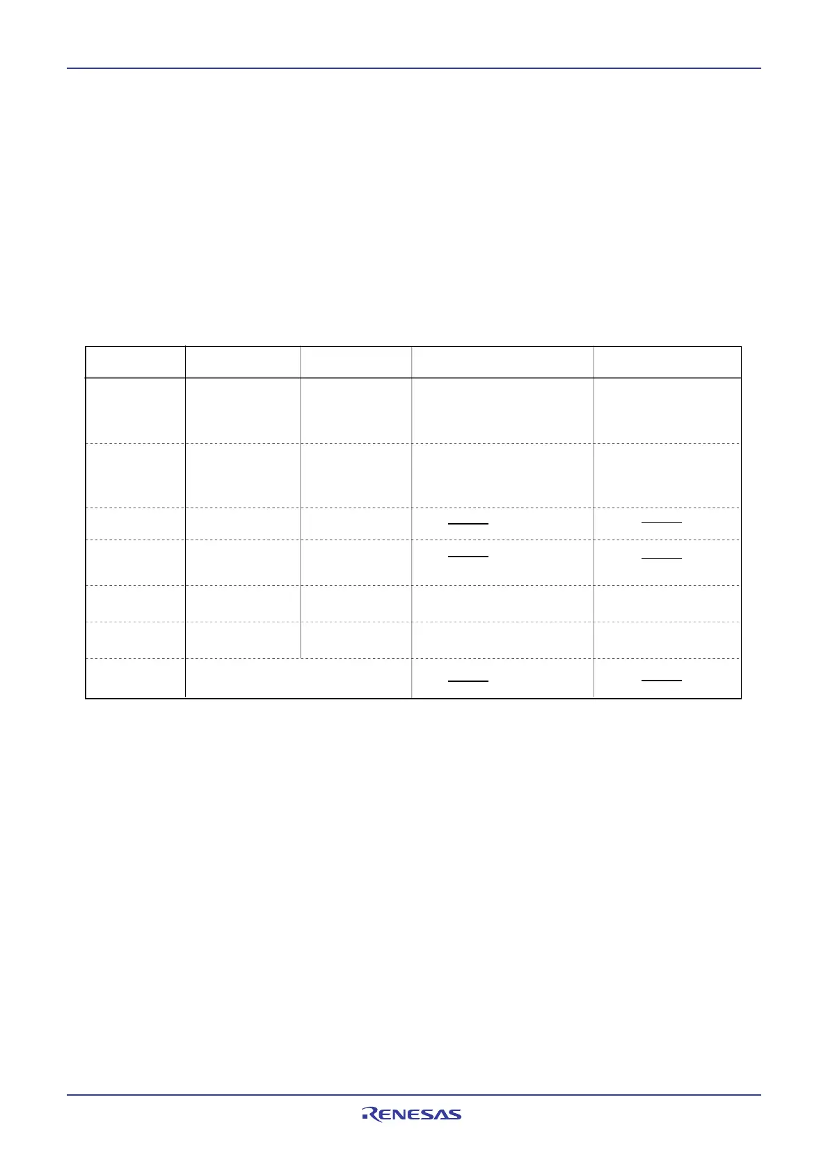
The clock generation circuit contains four oscillator circuits as follows:
(1) Main clock oscillation circuit
(2) Sub clock oscillation circuit
(3) Variable on-chip oscillators
(4) PLL frequency synthesizer
Table 7.1 lists the specifications of the clock generation circuit. Figure 7.1 shows the clock generation
circuit. Figures 7.2 to 7.7 show clock-associated registers.
Table 7.1 Clock Generation Circuit Specifications
 Loading...


