15. A/D Converter
puorG92/C61M
page 228
854fo7002,03.raM21.1.veR
2110-1010B90JER
15.1 Operating Modes
15.1.1 One-Shot Mode
In one-shot mode, analog voltage applied to a selected pin is once converted to a digital code. Table
15.3 shows the one-shot mode specifications. Figure 15.6 shows the operation example in one-shot
mode. Figure 15.7 shows registers ADCON0 to ADCON2 in one-shot mode.
Table 15.3 One-shot Mode Specifications
Item Specification
Function Bits CH2 to CH0 in the ADCON0 register and registers ADGSEL1 and
ADGSEL0 in the ADCON2 register select pins. Analog voltage applied to a
selected pin is once converted to a digital code
A/D Conversion Start
• When the TRG bit in the ADCON0 register is 0 (software trigger)
Condition
Set the ADST bit in the ADCON0 register to 1 (A/D conversion started)
• When the TRG bit in the ADCON0 register is 1 (hardware trigger)
The ADTRG pin input changes state from “H” to “L” after setting the
ADST bit to 1 (A/D conversion started)
A/D Conversion Stop • A/D conversion completed (If a software trigger is selected, the ADST bit is
Condition set to 0 (A/D conversion halted)).
• Set the ADST bit to 0
Interrupt Request Generation Timing
A/D conversion completed
Analog Input Pin
Select one pin from AN
0
to AN
7
, AN0
0
to AN0
7
, AN2
0
to AN2
7
, AN3
0
to AN3
2
Readout of A/D Conversion Result
Readout one of registers AD0 to AD7 that corresponds to the selected pin
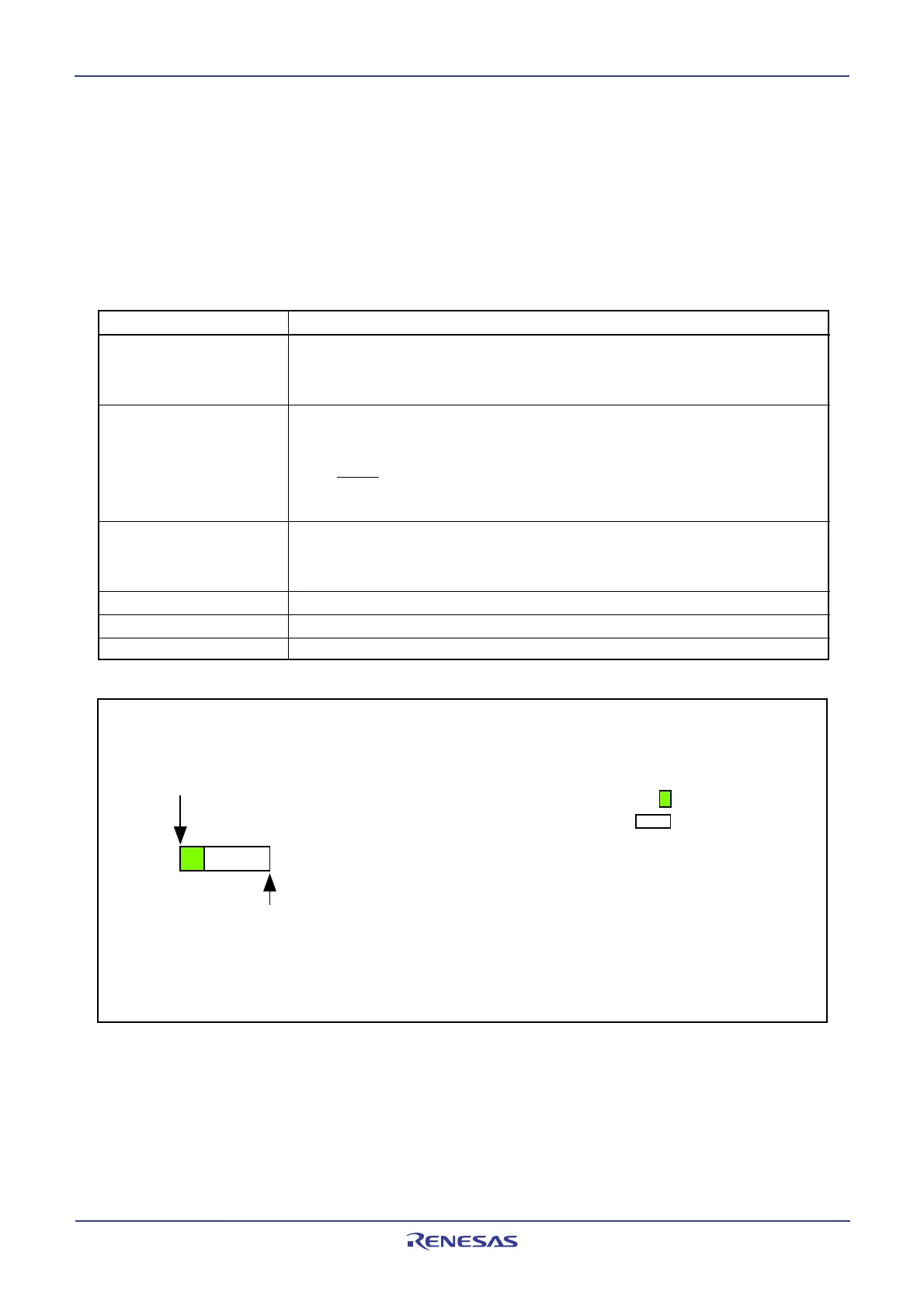
Figure 15.6 Operation Example in One-Shot Mode
•Example when selecting AN2 to an analog input pin (Ch2 to CH0 = 0102)
AN
0
AN1
AN2
AN3
AN4
AN5
AN6
AN7
A/D conversion started
A/D interrupt request generated
A/D pin input voltage
sampling
A/D pin conversion
 Loading...


