10. Watchdog Timer
puorG92/C61M
page 90
854fo7002,03.raM21.1.veR
2110-1010B90JER
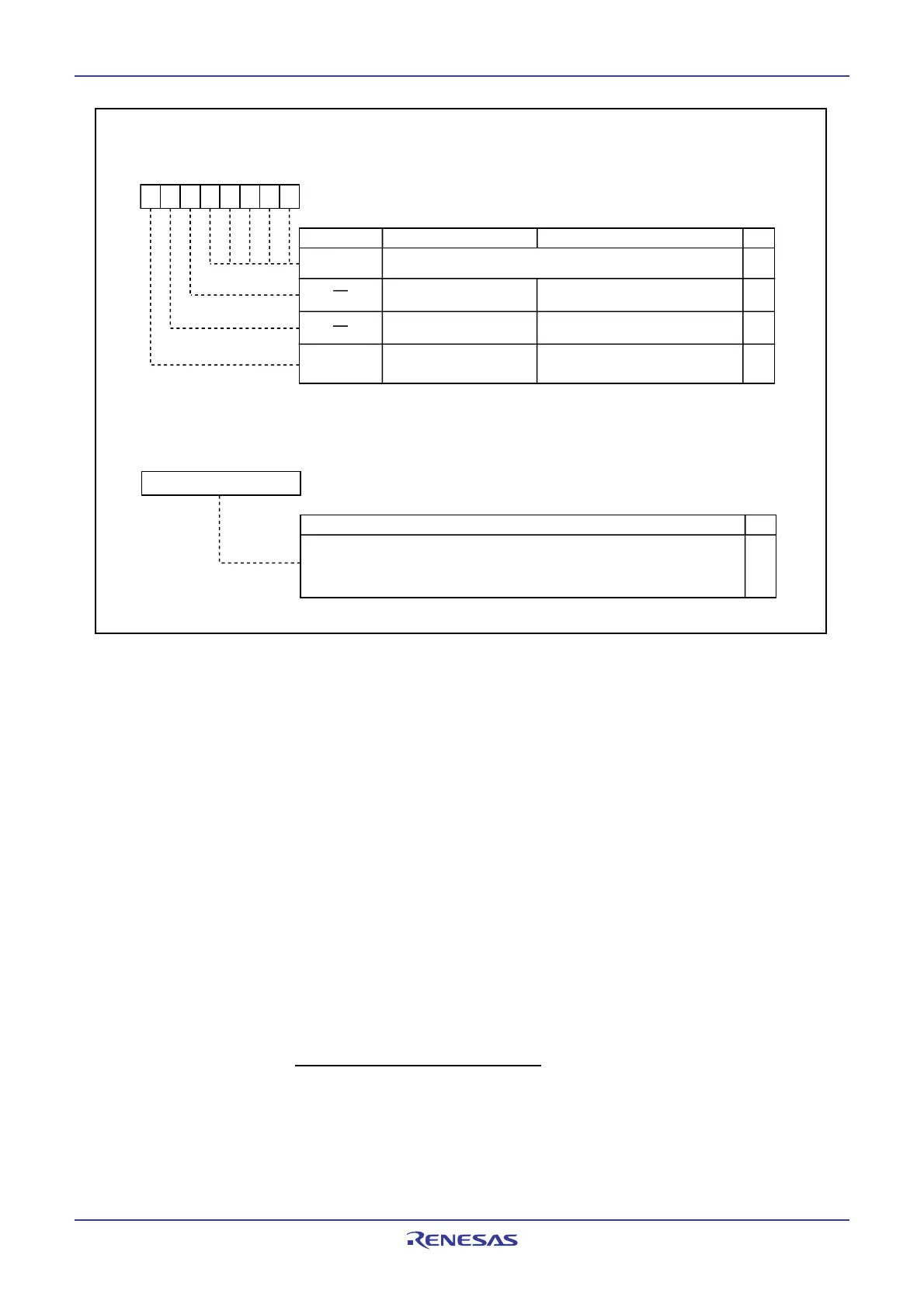
Figure 10.2 WDC Register and WDTS Register
10.1 Count Source Protective Mode
In this mode, a on-chip oscillator clock is used for the watchdog timer count source. The watchdog timer
can be kept being clocked even when CPU clock stops as a result of run-away.
Before this mode can be used, the following register settings are required:
(1) Set the PRC1 bit in the PRCR register to 1 (enable writes to PM1 and PM2 registers).
(2) Set the PM12 bit in the PM1 register to 1 (reset when the watchdog timer underflows).
(3)
Set the PM22 bit in the PM2 register to 1 (on-chip oscillator clock used for the watchdog timer count source).
(4) Set the PRC1 bit in the PRCR register to 0 (disable writes to PM1 and PM2 registers).
(5) Write to the WDTS register (watchdog timer starts counting).
Setting the PM22 bit to 1 results in the following conditions
• The on-chip oscillator continues oscillating even if the CM21 bit in the CM2 register is set to "0" (main clock
or PLL clock) (system clock of count source selected by the CM21 bit is valid)
• The on-chip oscillator starts oscillating, and the on-chip oscillator clock becomes the watchdog timer
count source.
•
The CM10 bit in the CM1 register is disabled against write. (Writing a 1 has no effect, nor is stop mode entered.)
• The watchdog timer does not stop when in wait mode.
Watchdog timer period =
Watchdog timer count (32768)
on-chip oscillator clock
Watchdog Timer Start Register
Symbol Address After Reset
WDTS 000E
16
Undefine d
WO
b7 b0
Function
RW
The watchdog timer is initialized and starts counting after a write instruction
to this register. The watchdog timer value is always initialized to 7FFF
16
regardless of whatever value is written.
Watchdog Timer Control Register
Symbol Addres s After Reset
WDC 000F
16 00XXXXXX2
FunctionBit Symbol
RW
b7 b6 b5 b4 b3 b2 b1 b0
High-order bits of watchdog timer
WDC7
Bit Name
Prescaler select bit
0 : Divided by 16
1 : Divided by 12
8
Reserved bit
Set to 0
0
RO
RW
RW
RW
(b4-b0)
(b6)
0
(b5)
Reserved bit
Set to 0
 Loading...


