16. MULTI-MASTER I
2
C bus INTERFACE
puorG92/C61M
page 281
854fo7002,03.raM21.1.veR
2110-1010B90JER
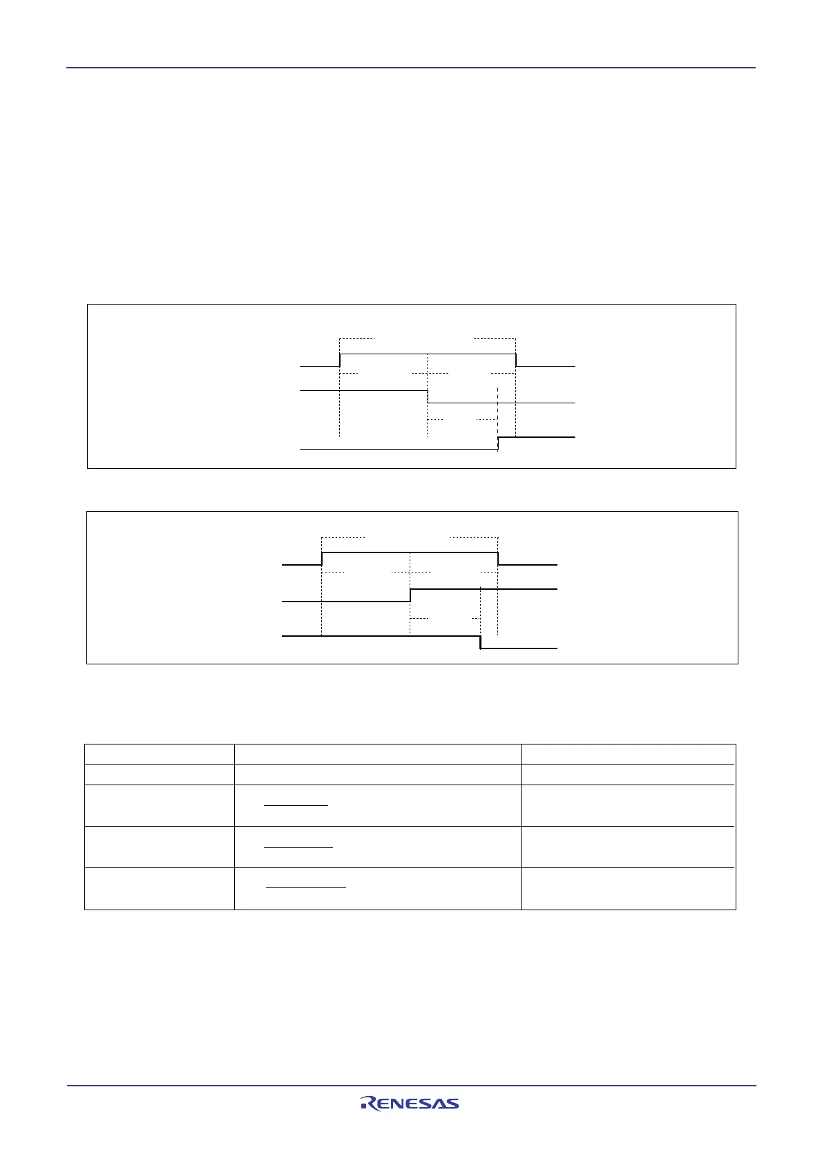
16.12 START/STOP Condition Detect Operation
Figure 16.18, Figure 16.19 and Table 16.10 show START/STOP condition detect operations. Bits SSC4
to SSC0 in the S2D0 register set the START/STOP conditions. The START/STOP condition can be de-
tected only when the input signal of the SCLMM and SDAMM met the following conditions: the SCL release
time, the set-up time, and the hold time (see Table 16.10). The BB flag in the S10 register is set to 1 when
the START condition is detected and it is set to 0 when the STOP condition is detected. The BB flag set and
reset timing varies between standard clock mode and high-speed clock mode. See Table 16.10.
Figure 16.18 Start condition detection timing diagram
Figure 16.19 Stop condition detection timing diagram
Standard clock mode High-speed clock mode
SCL release time SSC value + 1 cycle (6.25µs) 4 cycles (1.0µs)
Setup time SSC value + 1 cycle < 4.0µs (3.25µs) 2 cycles (0.5µs)
2
Hold time SSC value cycle < 4.0µs (3.0µs) 2 cycles (0.5µs)
2
BB flag set/reset SSC value - 1 +2 cycles (3.375µs) 3.5 cycles (0.875µs)
time 2
Table 16.10 Start/Stop detection timing table
S
CL
release time
Hold timeSetup time
BB flag
set time
BB flag
S
DA
S
CL
BB flag
S
DA
SCL
SCL release time
Hold time
Setup time
BB flag
set time
NOTE:
1. Unit : number of cycle for I
2
C system clock VIIC
The SSC value is the decimal notation value of bits SSC4 to SSC0. Do not set 0 or odd numbers to the SSC
setting. The values in ( ) are examples when the S2D0 register is set to 1816 at VIIC = 4 MHz.
 Loading...


