14. Serial I/O
puorG92/C61M
page 196
854fo7002,03.raM21.1.veR
2110-1010B90JER
14.1.3 Special Mode 1 (I
2
C bus mode)(UART2)
I
2
C bus mode is provided for use as a simplifed I
2
C bus interface compatible mode. Table 14.10 lists the
specifications of the I
2
C bus mode. Tables 14.11 and 14.12 list the registers used in the I
2
C bus mode
and the register values set. Table 14.13 lists the I
2
C bus mode fuctions. Figure 14.22 shows the block
diagram for I
2
C bus mode. Figure 14.23 shows SCL2 timing.
As shown in Table 14.13, the MCU is placed in I
2
C bus mode by setting bits SMD2 to SMD0 to 0102 and
the IICM bit to 1. Because SDA2 transmit output has a delay circuit attached, SDA output does not
change state until SCL2 goes low and remains stably low.
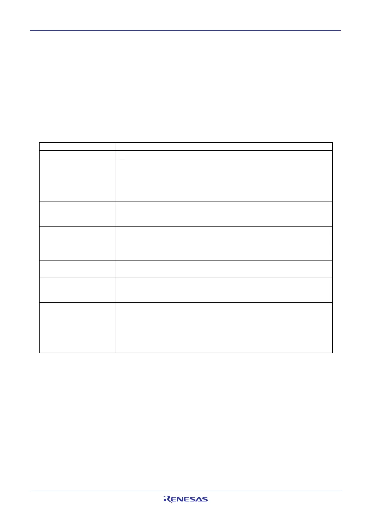
Table 14.10 I
2
C bus mode Specifications
Item Specification
Transfer data format • Transfer data length: 8 bits
Transfer clock • During master
the CKDIR bit in the U2MR register is set to 0 (internal clock) : fj/ (2(n+1))
fj = f
1SIO, f2SIO, f8SIO, f32SIO. n: Setting value in the U2BRG register 0016 to FF16
• During slave
CKDIR bit is set to 1 (external clock ) : Input from SCL2 pin
Transmission start condition • Before transmission can start, the following requirements must be met
(1)
_
The TE bit in the U2C1 register is set to 1 (transmission enabled)
_
The TI bit in the U2C1 register is set to 0 (data present in U2TB register)
Reception start condition • Before reception can start, the following requirements must be met
(1)
_
The RE bit in the U2C1 register is set to 1 (reception enabled)
_
The TE bit in the U2C1 register is set to 1 (transmission enabled)
_
The TI bit in the U2C1 register is set to 0 (data present in the UiTB register)
When start or stop condition is detected, acknowledge undetected, and acknowledge
detected
Error detection • Overrun error
(2)
This error occurs if the serial I/O started receiving the next data before reading the
U2RB register and received the 8th bit in the the next data
Select function • Arbitration lost
Timing at which the ABT bit in the U2RB register is updated can be selected
• SDA digital delay
No digital delay or a delay of 2 to 8 U2BRG count source clock cycles selectable
• Clock phase setting
With or without clock delay selectable
Interrupt request
generation timing
NOTES:
1. When an external clock is selected, the conditions must be met while the external clock is in the high
state.
2. If an overrun error occurs, bits 8 to 0 in the U2RB register are undefined. The IR bit in the S2RIC
register remains unchange.
 Loading...


