7. Clock Generation Circuit
page 61
854fo7002,03.raM21.1.veR
2110-1010B90JER
puorG92/C61M
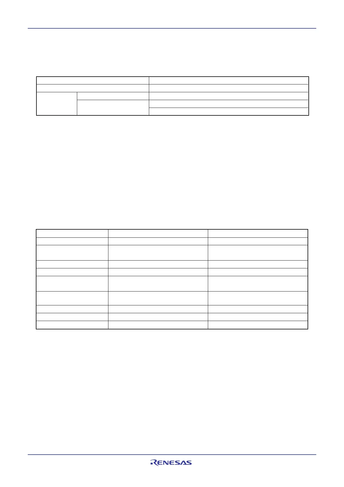
Table 7.6 Interrupts to Exit Wait Mode
Interrupt CM02 = 0 CM02 = 1
NMI interrupt Available Available
Serial I/O interrupt Available when internal and external Available when external clock is used
clocks are used
Multi-master I
2
C interrupt Available Do not used
Key input interrupt Available Available
A/D conversion interrupt Available in one-shot or single sweep Do not use
mode
Timer A interrupt Available in all modes Available in event counter mode or when
Timer B interrupt count source is fC32
Timer S interrupt Available in all modes Do not use
_______
INT interrupt Available Available
CAN0 wake_up interrupt Available in CAN sleep mode Available in CAN sleep mode
7.6.2.3 Pin Status During Wait Mode
Table 7.5 lists pin status during wait mode.
Table 7.5 Pin Status in Wait Mode
Pin Status
I/O ports Retains status before wait mode
When fC selected Does not stop
CLKOUT When f1, f8, f32 selected Does not stop when the CM02 bit is set to 0
Retains status before wait mode when the CM02 bit is set to 1
To use peripheral function interrupts to exit wait mode, set the followings before executing the WAIT
instruction.
1. Set the interrupt priority level to the bits ILVL2 to ILVL0 in the interrupt control register of the periph-
eral function interrupts that are used to exit wait mode. Also, set bits ILVL2 to ILVL0 of all peripheral
function interrupts that are not used to exit wait mode to 000
2
(interrupt disabled).
2. Set the I flag to 1.
3. Operate the peripheral functions that are used to exit wait mode.
When the peripheral function interrupts are used to exit wait mode, an interrupt routine is executed
after an interrupt request is generated and the CPU is clocked.
The CPU clock used when exiting wait mode by a peripheral function interrupt is the same CPU clock
that is used when executing the WAIT instruction.
7.6.2.4 Exiting Wait Mode
______
The MCU exits from wait mode by a hardware reset, NMI interrupt, or peripheral function interrupt.
______
If wait mode is exited by a hardware reset or NMI interrupt, set the peripheral function interrupt priority
bits ILVL2 to ILVL0 to 000
2
(interrupts disabled) before executing the WAIT instruction.
The CM02 bit affects the peripheral function interrupts. If the CM02 bit is 0 (peripheral function clocks
not turned off during wait mode), all peripheral function interrupts can be used to exit wait mode. If the
CM02 bit is 1 (peripheral function clock stops during wait mode), the peripheral functions using the
peripheral function clock stops operating, so that only the peripheral functions clocked by external sig-
nals can be used to exit wait mode.
Table 7.6 lists the interrupts to exit wait mode.
 Loading...


