9. Interrupts
puorG92/C61M
page 88
854fo7002,03.raM21.1.veR
2110-1010B90JER
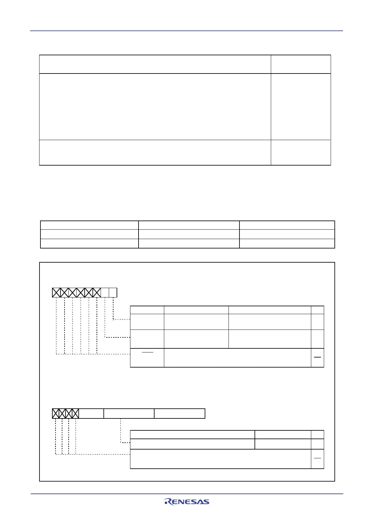
Figure 9.14 AIER Register, RMAD0 and RMAD1 Registers
• 2-byte op-code instruction
• 1-byte op-code instructions which are followed:
ADD.B:S #IMM8,dest SUB.B:S #IMM8,dest AND.B:S #IMM8,dest
OR.B:S #IMM8,dest MOV.B:S #IMM8,dest STZ.B #IMM8,dest
STNZ.B #IMM8,dest STZX.B #IMM81,#IMM82,dest
CMP.B:S #IMM8,dest PUSHM src POPM dest
JMPS #IMM8 JSRS #IMM8
MOV.B:S #IMM,dest (However, dest=A0 or A1)
Instructions other than the above
Instruction at the address indicated by the RMADi register
Value of the PC that is
saved to the stack area
The address
indicated by the
RMADi register +2
The address
indicated by the
RMADi register +1
Value of the PC that is saved to the stack area : Refer to “Saving Registers”.
Op-code is an abbreviation of Operation Code. It is a portion of instruction code.
Refer to Chapter 4 Instruction Code/Number of Cycles in M16C/60, M16C/20 Series Software Manual. Op-code is shown
as a bold-framed figure directly below the Syntax.
Table 9.7 Relationship Between Address Match Interrupt Sources and Associated Registers
Address match interrupt sources Address match interrupt enable bit Address match interrupt register
Address match interrupt 0 AIER0 RMAD0
Address match interrupt 1 AIER1 RMAD1
Bit NameBit Symbol
Symbol Address After Reset
AIER 0009
16
XXXXXX00
2
Address Match Interrupt Enable Register
Function
RW
Address match interrupt 0
enable bit
0 : Interrupt disabled
1 : Interrupt enabled
AIER0
Address match interrupt 1
enable bit
AIER1
Symbol Address After Reset
RMAD0 0012
16
to 0010
16
X00000
16
RMAD1 0016
16
to 0014
16
X00000
16
b7 b6 b5 b4 b3 b2 b1 b0
Address setting register for address match interrupt
Function Setting Range
Address Match Interrupt Register i (i = 0 to 1)
00000
16
to FFFFF
16
0 : Interrupt disabled
1 : Interrupt enabled
b0 b7 b0b3
(b19) (b16)
b7 b0
(b15) (b8)
b7
(b23)
RW
RW
(b7-b2)
RW
RW
Nothing is assigned. If necessary, set to 0.
When read, the content is undefined
Nothing is assigned. If necessary, set to 0.
When read, the content is undefined
Table 9.6 PC Value Saved in Stack Area When Address Match Interrupt Request Is Acknowledged
 Loading...


