13. Timer S
puorG92/C61M
page 160
854fo7002,03.raM21.1.veR
2110-1010B90JER
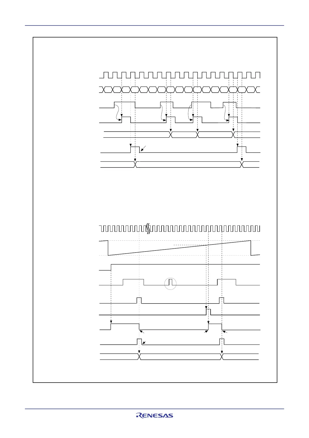
Figure 13.21 Prescaler Function and Gate Function
NOTE:
1. Bits in the G1IR register.
G1IRj bit
(1)
fBT1
fBT1
Base timer
G1IRj bit
(2)
G1TMj register
Internal time
measurement trigger
Prescaler
(1)
(a) With the prescaler function
(When the G1TPRj register (j = 6, 7) is set to 02
16
, the PR bit in the G1TMCRj register (j = 6, 7) is set to 1)
Base timer
INPC1j pin input or
trigger signal after
passing the digital
filter
Internal time
measurement trigger
IFEj bit in G1FE
register
G1POk register
match signal
Gate control signal
G1TMj register
Value of the G1POk register
This trigger input is disabled
due to gate function
.
21
0
FFFF
16
0000
16
n-2 n-1 n n+2 n+3 n+4 n+5 n+6 n+7 n+8 n+9 n+10 n+11 n+14
n+
1
n+13
2
(b) With the gate function
(The gate function is cleared by matching the base timer with the G1POk register(k = 4, 5),
the GT bit in the G1TMCRj register is set to 1, the GOC bit is set to 1)
INPC1j pin input or
trigger signal after
passing the digital
filter
Set 0 by program if necessary
Set 0 by program if necessary
Gate
Gate
Gate cleared
n+1 +12 n+13
NOTES:
1. This applies to 2nd or later prescaler cycle after the PR bit in the G1TMCRj register is set to 1 (prescaler used).
2. Bits in the G1IR register.
 Loading...


