17. CAN Module
puorG92/C61M
page 296
854fo7002,03.raM21.1.veR
2110-1010B90JER
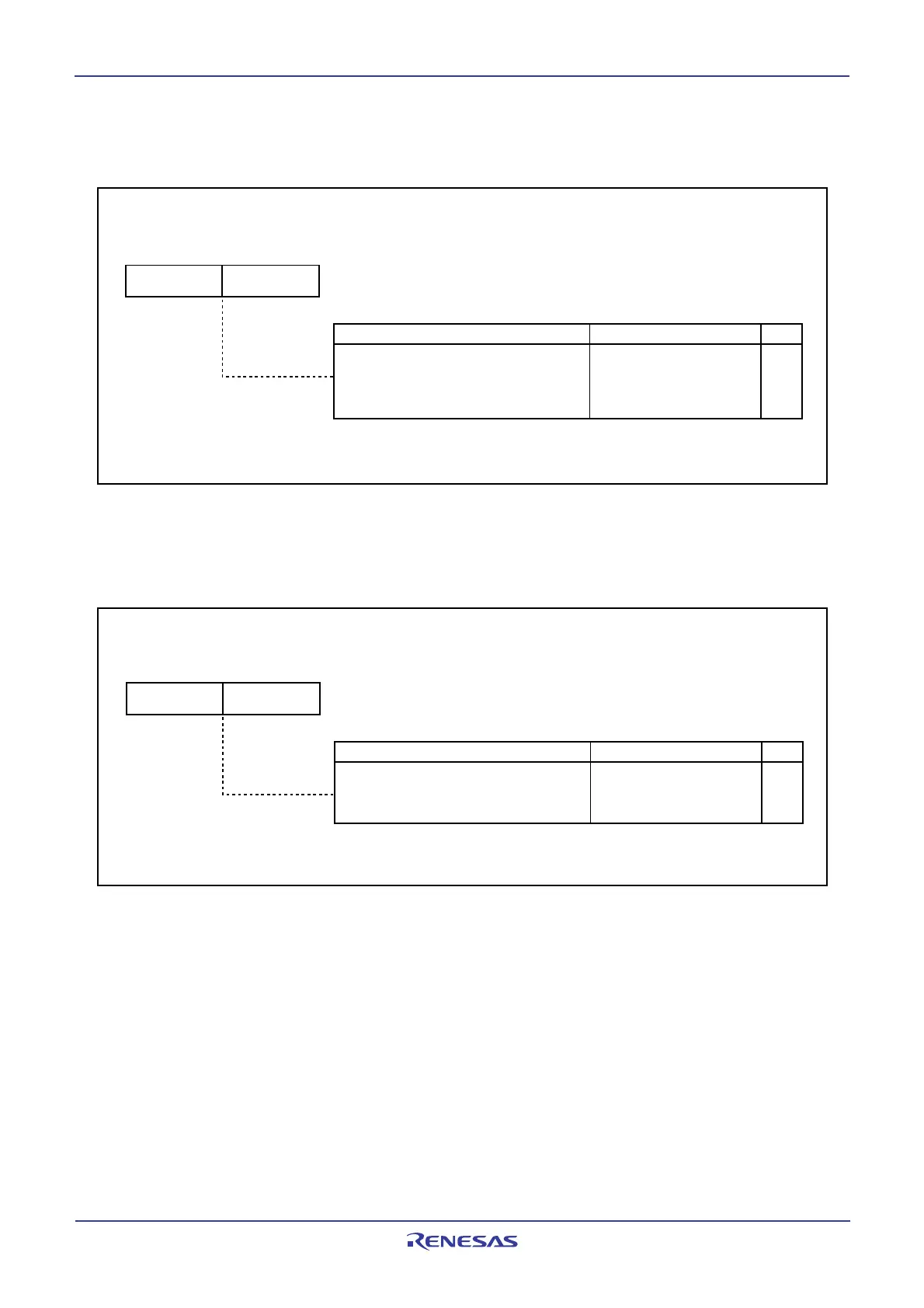
Figure 17.10 C0ICR Register
17.1.3.6 C0IDR Register
Figure 17.11 shows the C0IDR register.
17.1.3.5 C0ICR Register
Figure 17.10 shows the C0ICR register.
Figure 17.11 C0IDR Register
CAN0 Interrupt Control Register
(1)
(b15) (b8)
b0b0 b7b7
Function
Setting Values
Interrupt enable bits:
Each bit corresponds with a slot with the same
number.
Enabled/disabled of successful transmission inter-
rupt or successful reception interrupt can be selected
0: Interrupt disabled
1: Interrupt enabled
RW
RW
Symbol
Address After Reset
C0ICR 0217
16
, 0216
16
0000
16
NOTE:
1.
Set the C0ICR register only when the CAN module is in CAN operating mode.
CAN0 extended ID register
(1)
Symbol
Address
After Reset
C0IDR 0219
16
, 0218
16
0000
16
(b15) (b8)
Function
Setting Values
b0b0 b7b7
RW
RW
Extended ID bits:
Each bit corresponds with a slot with the same
number.
Selection of the ID format that each slot handles
0: Standard ID
1: Extended ID
NOTE:
1.
Set the C0IDR register only when the CAN module is in CAN operating mode.
 Loading...


