Key-Input Interrupt
M30240 Group
Rev.1.00 Sep 24, 2003 Page 272 of 360
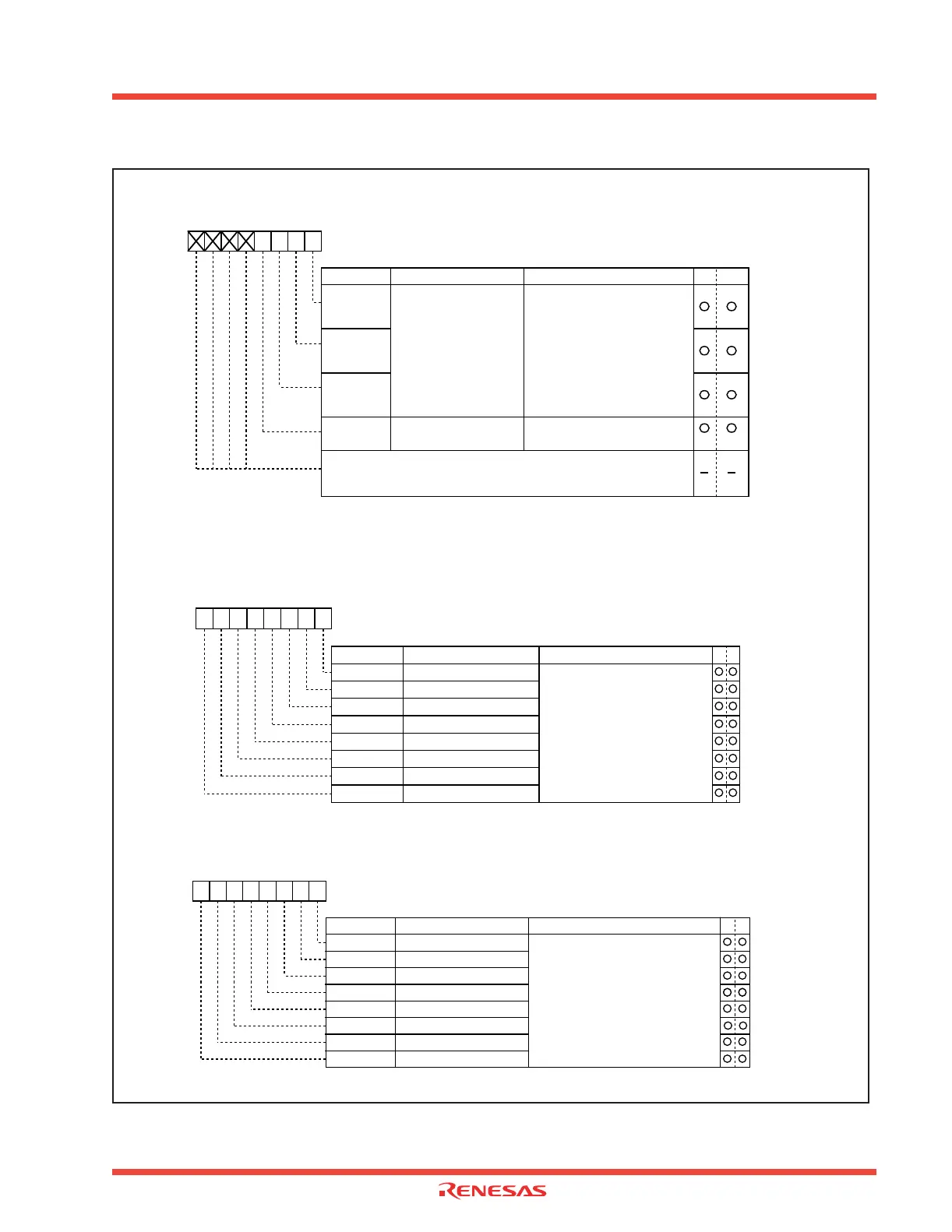
Figure 2.120: Key-input interrupt-related registers
b7 b6 b5 b4 b3 b2 b1 b0
Bit name FunctionBit symbol
WR
ILVL0
IR
Interrupt priority level
select bit
Interrupt request bit
0 : Interrupt not requested
1 : Interrupt requested
ILVL1
ILVL2
Nothing is assigned.
These bits can neither be set nor reset. When read, their contents are
indeterminate.
(Note1)
Note 1: This bit can only be reset (= 0). It cannot
be set
(= 1).
0 0 0 : Level 0 (interrupt disabled)
0 0 1 : Level 1
0 1 0 : Level 2
0 1 1 : Level 3
1 0 0 : Level 4
1 0 1 : Level 5
1 1 0 : Level 6
1 1 1 : Level 7
b2 b1 b0
Interrupt control register (Note 2)
Symbol
Address
When reset
KUPIC
004D
16
XXXX0000
2
Symbol Address When reset
PDi (i = 0,
1)
03E216, 03E316 0016
Port Pi direction register
Bit name FunctionBit symbol WR
b7 b6 b5 b4 b3 b2 b1 b0
PDi_0 Port Pi0 direction register
PDi_1 Port Pi
1 direction register
PDi_2 Port Pi
2 direction register
PDi_3 Port Pi
3 direction register
PDi_4 Port Pi
4 direction register
PDi_5 Port Pi
5 direction register
PDi_6 Port Pi
6 direction register
PDi_7 Port Pi
7 direction register
0 : Input mode
(Functions as an input port)
1 : Output mode
(Functions as an output port)
(i = 0, 1)
Pull-up control register 0
Symbol Address
When reset
PUR0
03FC16
0016
Bit name FunctionBit symbol WR
b7 b6 b5 b4 b3 b2 b1 b0
PU00 P00 to P03 pull-up
The corresponding port is pulled high
with a pull-up resistor
0 : Not pulled high
1 : Pulled high
PU01 P04 to P07 pull-up
PU02 P1
0 to P13 pull-up
PU03 P1
4 to P17 pull-up
PU04 P2
0 to P23 pull-up
PU05 P2
4 to P27 pull-up
PU06 P3
0 to P33 pull-up
PU07 P3
4 to P37
Note 2: To rewrite the interrupt control register, do so when it would not generate an interrupt
request for that register. See the Interrupt precautions section for more details.
 Loading...


