Overview of Interrupts
M30240 Group
Rev.1.00 Sep 24, 2003 Page 345 of 360
4.1.6 Precautions
4.1.6.1 Reading address 00000
16
• When a maskable interrupts occurs, the CPU reads the interrupt information (the interrupt number
and interrupt request level) in the interrupt sequence.
• The interrupt request bit of the corresponding interrupt written in address 00000
16
is then set to “0”.
• Do not read address 00000
16
by software.
• Reading address 00000
16
by software sets the highest priority enabled interrupt source request bit to “0”
Therefore the interrupt routine may not be executed even though the interrupt is generated.
4.1.6.2 Setting the stack pointer
• The value of the stack pointer is initialized to 00000
16
immediately after reset. Accepting an interrupt
before setting a value in the stack pointer may cause program runaway. Be sure to set a value in the
stack pointer before accepting an interrupt.
• When using the NMI
interrupt, initialize the stack pointer at the beginning of a program. Concerning
the first instruction immediately after reset, generating any interrupts including the NMI
interrupt is
prohibited.
4.1.6.3 Setting interrupts
• Changing the Interrupt Priority Level select bit (ILVL) and clearing the Interrupt Request bit (IR) in
the Interrupt Control Registers (ICR) while the Interrupt enable flag (I-flag) is “1”, may result in unin-
tended operations, such as BRK and other interrupts being generated. Disable the interrupts by
clearing the I-FLAG before setting ILVL or clearing the IR bit.
• To prevent the I-FLAG from being set before the ICR is rewritten due to the effects of the instruction
queue, instructions that equal a minimum of 2 cycles should be inserted between writing to the ICR
and setting the I-FLAG (2-NOPs, I MOV, I POP, etc.)
Modifying interrupt control registers
• Do not modify any interrupt control register when an interrupt request can be generated.
• If an interrupt request occurs, modify the interrupt control register after the interrupt is disabled.
4.1.6.4 External interrupts
• When the polarity of the INT0 and INT1 pins is changed, the interrupt request bit can be set to “1”.
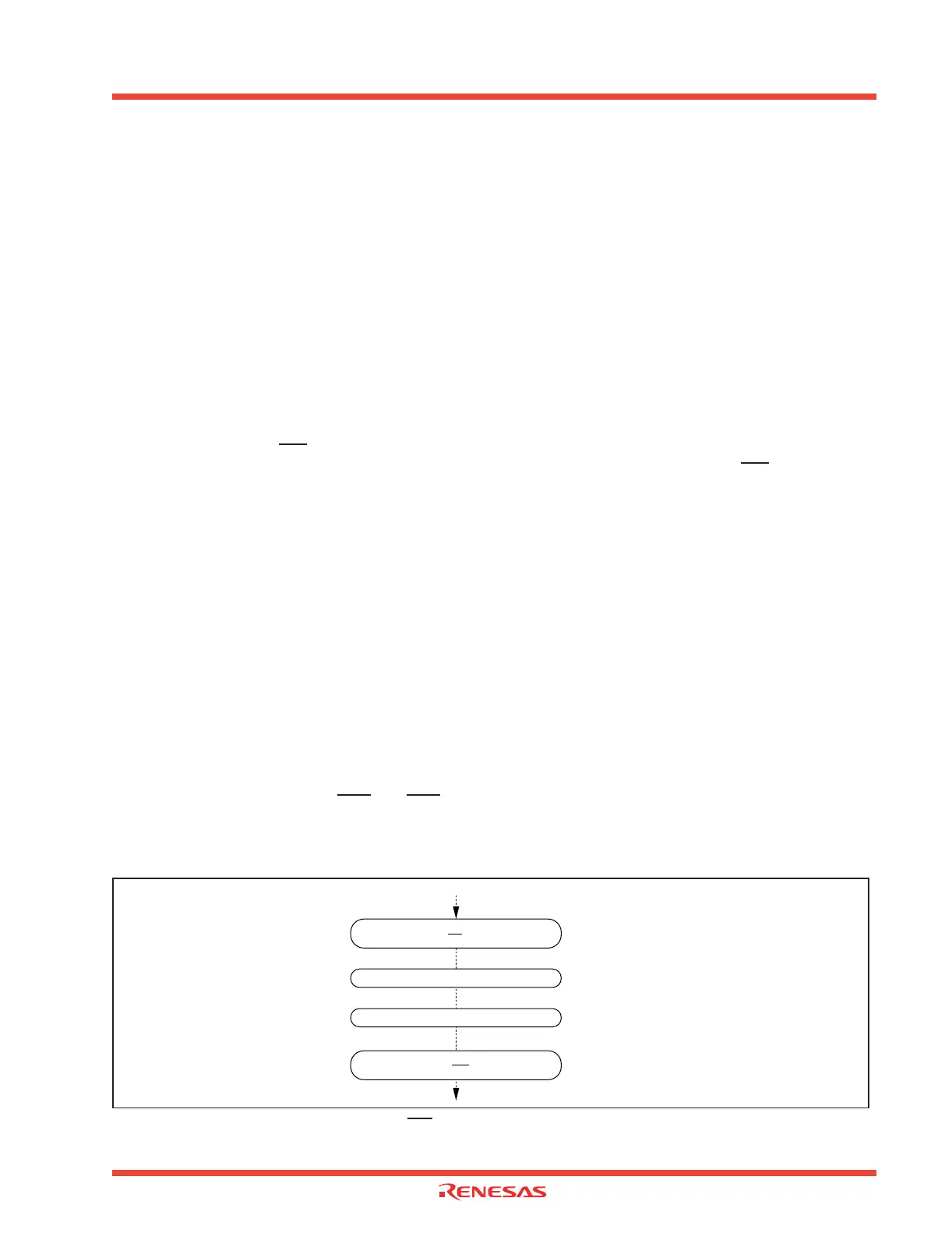
After changing the polarity, the interrupt request bit should be cleared to “0.” Figure 4.10 shows the
procedure for changing the INT interrupt select bit.
Figure 4.10: Changing the condition of INT interrupt request
Set the interrupt priority level to level 0
(Disable
INTi interrupt)
Set the polarity select bit
Clear the interrupt request bit to “0”
Set the interrupt priority level to level 1 to 7
(Enable the INTi interrupt)
 Loading...


